Sinking container positioning and floating device

A container and reaction device technology, applied in measurement devices, satellite radio beacon positioning systems, buoys, etc., can solve problems such as inaccurate positioning, high diving risk, and complex underwater machines.

Active Publication Date: 2019-11-19
SHANGHAI MARITIME UNIVERSITY
View PDF9 Cites 0 Cited by
  • Summary
  • Abstract
  • Description
  • Claims
  • Application Information

AI Technical Summary

Problems solved by technology

Active detection usually uses imaging sonar and laser imaging technology to detect underwater containers. Active detection is greatly affected by the underwater environment and cannot be accurately located.
There are two main methods of buoy positioning. The first is that the crew puts the positioning device on the falling container in time. This kind of positioning is difficult for the crew to put it in time under adverse weather conditions or ship collisions. make it impossible to locate
The second type uses an automatic inflator for water entry. The inflator needs to be replaced every time it works, and it occupies a large volume, which is inconvenient for storage and installation.
[0004] Container flotation methods are mainly personnel diving and robot diving: it is more accurate to install floating devices for personnel diving, but personnel diving is greatly affected by the ocean environment and underwater depth, and the risk of diving is relatively high, generally not at special times Will personnel be used to dive to salvage containers?
Robotic diving is to install the floating device to the underwater container through the underwater robot. The robot diving solves the high risk of personnel diving, but the underwater machine is more complicated to work underwater, difficult to operate, low in efficiency, and high in cost.

Method used


Image

  • Sinking container positioning and floating device
  • Sinking container positioning and floating device
  • Sinking container positioning and floating device

Examples


Embodiment Construction

[0020] The following will clearly and completely describe the technical solutions in the embodiments of the present invention with reference to the drawings in the embodiments of the present invention.

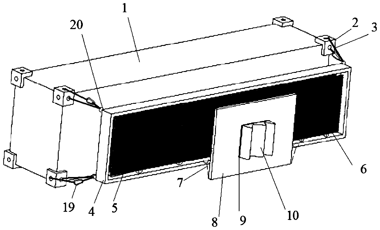
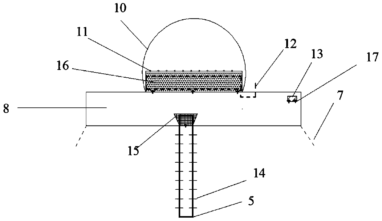
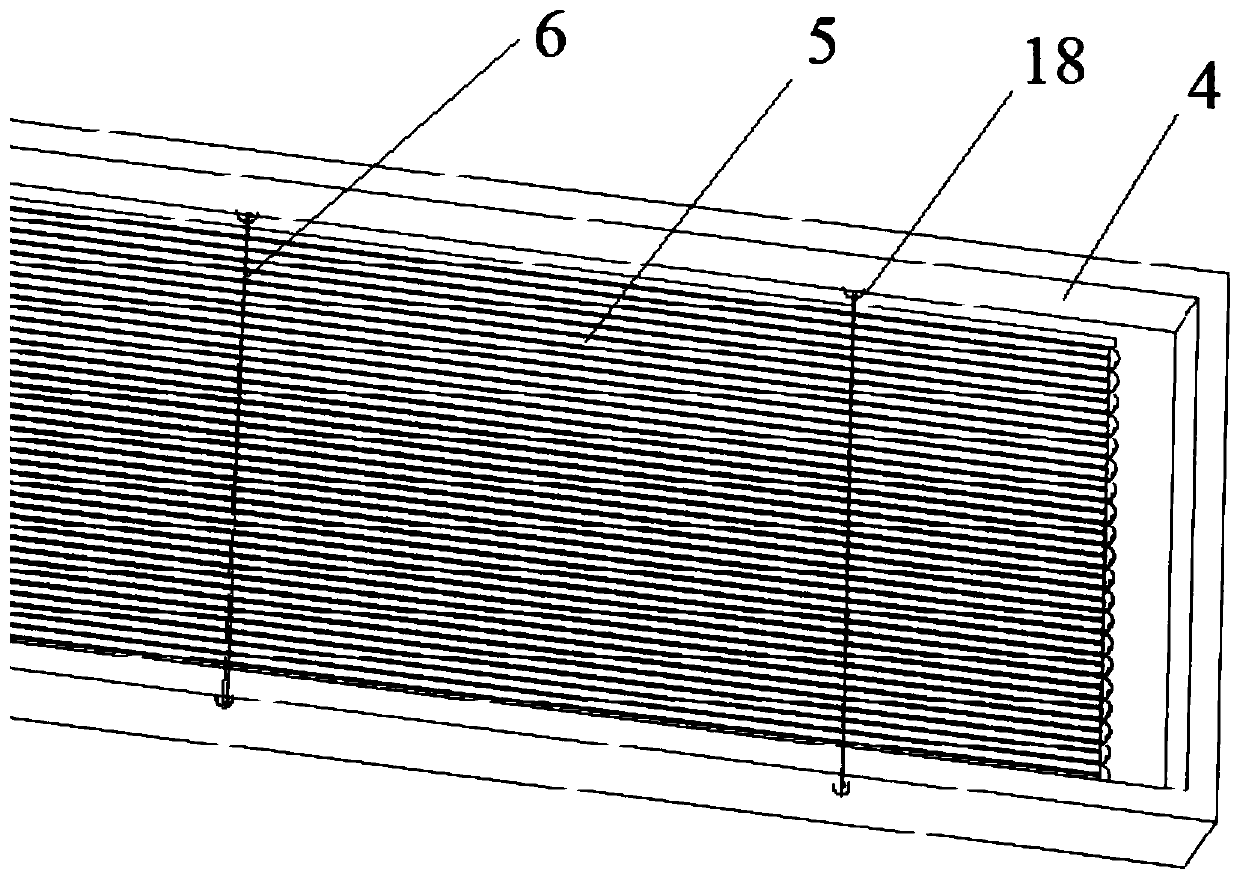
[0021] Such as Figures 1 to 3 As shown, the present invention provides a technical solution: a positioning and floating device for falling into the water container, including a floating airbag device, a high-pressure scale air pipe and a buoy material device.

[0022] The buoy material device includes a buoyancy material 8, a CO2 reaction device 9, and a gas-collecting airbag 10. The buoyancy material 8 is connected with a water-soluble thread 7, and the water-soluble thread 7 is connected with a floating airbag ring 18. After the container falls into the water, the seawater is soaked in a water-soluble After the linear line 7, the buoyancy material 8 will float up, and the CO2 reaction device 9 is connected with the buoyancy material 8 with a bolted fixture 17. There are alu...


PUM


Abstract

The invention discloses a sinking container positioning and floating device. By means of the advantages of dual positioning and dual buoyancy, a sinking container is quickly and accurately positionedand rapidly floats. A GPS positioning chip is installed on a buoyancy material, and a gas collection gas bag floats to the sea level and plays a role in secondary positioning. After the container falls overboard, the buoyancy material of a buoy material device can drive a high pressure scale gas pipe to float, the gas collection gas bag collects the CO2 gas, and the gas collection gas bag and thebuoyancy material provide the dual buoyancy for the high pressure scale gas pipe together. The position of the sinking container is judged through the scale on the high pressure scale gas pipe, the gas is supplied by the high pressure scale gas pipe to a floating gas bag, and the buoyancy of the floating gas bag drives the sinking container to float to the sea level. The sinking container positioning and floating device can solve the problem that the sinking container is difficult to position and inconvenient to fish. The sinking container positioning and floating device is convenient to operate and does not affect navigation. The underwater diving operation of workers or robots is not required, the sinking container can quickly float to the sea level, the fishing efficiency is improved, and the economic loss of a shipowner is reduced.

Description

technical field [0001] The invention relates to marine engineering technology, belongs to the technical field of underwater salvage, and in particular relates to a positioning and floating device for a container falling into the water. Background technique [0002] With the development of economy and trade, the position and role of container transportation in the national economic development of various countries are becoming more and more prominent. Due to its relatively high safety and low transportation costs, waterway transportation is one of the main methods of container transportation. There are a large number of container carriers traveling in inland rivers and offshore waterways. Due to adverse weather conditions, unfavorable channel conditions, dense ship traffic flow distribution, and operational errors by ship drivers, etc., accidents of container falling into the water often occur. If the sunken container is not salvaged in time, it will not only cause cargo los...

Claims


Application Information

Patent Timeline
IPC IPC(8): B63B35/00B63B22/00G01S19/14
CPCB63B22/00B63B35/00G01S19/14
Inventor 袁东林顾彩香邓伟涛
Owner SHANGHAI MARITIME UNIVERSITY
Why Eureka
Try Eureka