
Engine cooling system water way flushing tool and method

An engine cooling and engine technology, applied in engine cooling, engine components, machines/engines, etc., can solve the problems of low test efficiency, increase test cost, unfavorable foreign matter discharge, etc., achieve high test flushing efficiency, reduce test cost, Time-effective effect

Active Publication Date: 2019-11-19
Y & C ENGINE
View PDF5 Cites 0 Cited by
  • Summary
  • Abstract
  • Description
  • Claims
  • Application Information

AI Technical Summary

Problems solved by technology

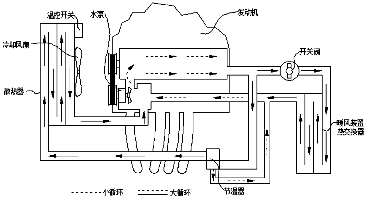
[0006] The first method: press each part in the cooling system of the engine figure 1 The connection method in is connected well, and in figure 1 Install the filter element at the water outlet of the large circulation in the engine, then start the engine to work, and perform the flushing operation under hot conditions, but this kind of operation method has to wait until the engine is working for a period of time, so that the temperature of the coolant reaches the opening temperature of the thermostat ( 80°C), it needs to wait for a period of time, the test efficiency is low, and the test consumes fuel, which increases the cost of the test, and it is necessary to wait until the engine cylinder is completely cooled before disassembling and replacing the next engine test, the test flushing efficiency is low
[0007] The second type: press each part in the cooling system of the engine figure 1 The connection method in is connected well, and in figure 1 A filter element is installed at the water outlet of the large circulation in the engine, and a water heating system is connected in parallel to the water inlet and outlet pipes of the radiator. When the engine is not started, the water pump is started to pump the hot water heated by the external heat source into the engine cooling water. Cavity or water channel, external heat source to heat water, also need to wait for a certain period of time, the test efficiency is low, also need energy to heat water, consume fuel, increase the test cost, and wait until the cylinder block of the engine is completely cooled before disassembling and replacing the next engine The test, the test flushing efficiency is low
[0008] But when the engine's large cycle is turned on, the small cycle inside the engine is also smooth, and part of the coolant will make a small cycle inside the engine, which is not conducive to the discharge of foreign matter in the engine cooling water cavity or water channel.

Method used


Image

  • Engine cooling system water way flushing tool and method
  • Engine cooling system water way flushing tool and method
  • Engine cooling system water way flushing tool and method

Examples


Embodiment 1

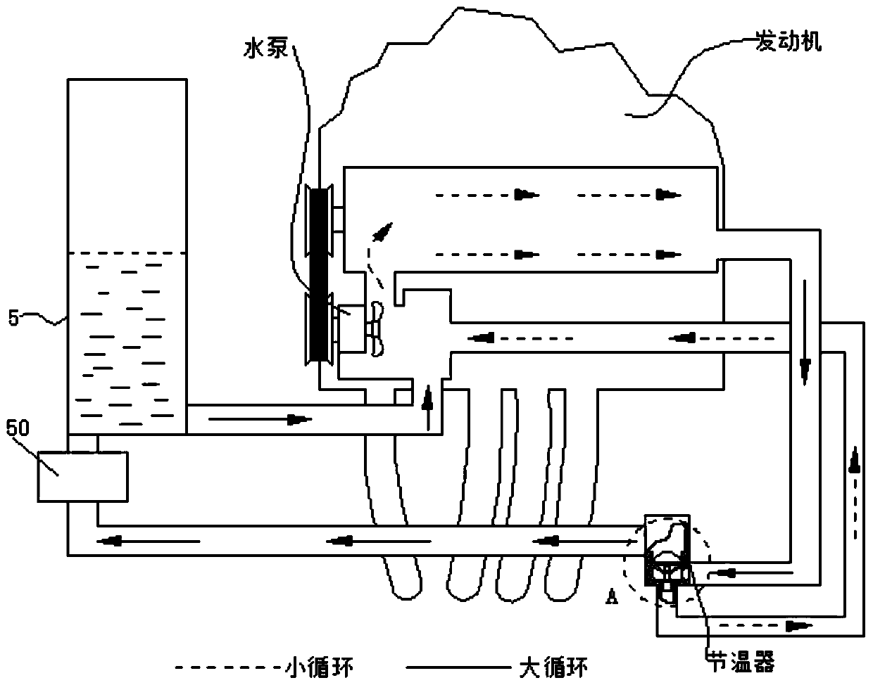
[0045] The engine cooling system waterway flushing tool replaces the radiator of the original engine cooling system with a water tank 5 for storing coolant, and then removes the temperature control system structure of the paraffin spring inside the traditional thermostat and replaces it with a symmetrical square platform Structural thermostat sealing ring 2 ensures that the large cycle of the cooling system is turned on and the small cycle is closed during the test. Under the action of the water pump, the starting water pump can be driven by an external power supply. At this time, the engine does not turn, and the starting water pump It is also possible to use an external power supply to drive the engine flywheel, so that the engine can be run cold for testing, and the coolant will take the foreign matter in the engine cooling water cavity or water channel out of the engine to achieve the purpose of flushing.

Embodiment 2

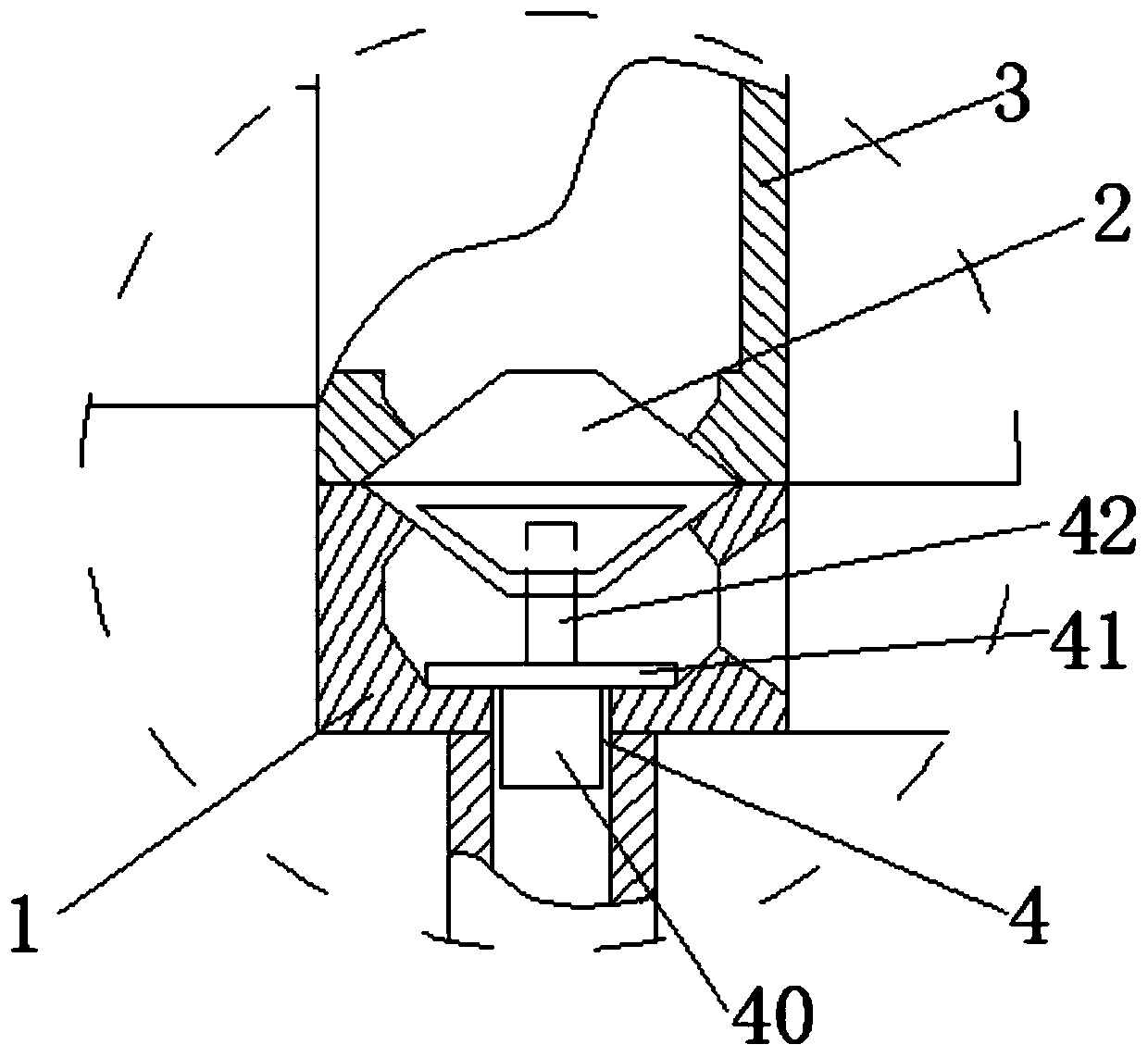
[0047] The water inlet and outlet of the water tank 5 are equipped with a filter element 50, which realizes the filtration of the foreign matter brought out by the coolant from the engine cooling water chamber or water channel; the thermostat cover 3 is fastened on the thermostat seat 1, and the A thermostat sealing ring 2 is arranged between the thermostat seat 1 and the thermostat cover 3, and the thermostat sealing ring 2 is a symmetrical quadrangular platform structure, which ensures the installation of the thermostat seat 1 and the thermostat cover 3 After completion of sealing; the bottom of the thermostat seat 1 is provided with diversion water plug tooling 4, and the bottom of the diversion water plug tooling 4 is a plunger 40, the middle is a retaining plate 41, the top is a pin 42, and the pin 42 is inserted into the joint The thermostat sealing ring 2 ensures the stability of the diversion water blocking tooling 4 under the impact of the large-circulation coolant flu...


PUM


Abstract

The invention discloses an engine cooling system water way flushing tool and method. A water outlet of a water tank is connected with a water inlet of a water pump. A filter element is arranged at a water inlet of the water tank and then is in communication connection with a water outlet in a thermostat cover. Cooling liquid is stored in the water tank. The thermostat cover is fastened to a thermostat base. A thermostat seal ring is arranged between the thermostat base and the thermostat cover. The thermostat seal ring is of a symmetric four-ridge table structure. A flow guiding water plug tool is arranged at the bottom of the thermostat base, the bottom of the flow guiding water plug tool is provided with a plunger, the middle is provided with a stop disc, the top end is provided with a bolt, the bolt is inserted in the thermostat seal ring, a tool thermostat without a temperature control system is used for assembling and testing, the large-cycle opening state is guaranteed, the smallcycle is closed, the cooling liquid brings foreign matter in an engine cooling water cavity or water way out of an engine, and the purpose of flushing is achieved. Under the situation that the engineis not started, the cold cooling liquid is directly adopted for flushing, the test cost is reduced, aging performance is good, and the testing and flushing efficiency is high.

Description

technical field [0001] The invention belongs to the technical field of electric motor detection, in particular, the invention relates to a water channel flushing tool and a flushing method of an engine cooling system Background technique [0002] The automobile engine cooling system is one of the six major systems of the engine. Its function is to dissipate part of the heat absorbed by the heated parts in time to ensure that the engine works at the most suitable temperature state. [0003] After the mixture gas is burned in the combustion chamber of the engine, high temperature and high pressure gas (about 800-2000°C) will be produced. Therefore, the cylinder must be cooled, otherwise the moving parts in it will expand due to heat and destroy the normal gap, the mechanical strength will be reduced and damaged, and the lubrication will fail and get stuck. If the cooling is excessive, it will also cause the reduction of cylinder filling volume, abnormal combustion, power redu...

Claims


Application Information

Patent Timeline
IPC IPC(8): F01P3/20F01P7/16F01P11/06
CPCF01P3/20F01P7/165F01P11/06F01P2011/061F01P2011/065
Inventor 吴家昌刘云川吴昊宋杨祁文胜
Owner Y & C ENGINE
Learn More