Automatic dispensing chip mounter for glass cup cover

An automatic dispensing and placement machine technology, applied in the direction of material gluing, mechanical equipment, connecting components, etc., can solve the problems of incomplete cleaning, inconvenient dispensing and placement process, wire drawing and tailing, etc., and achieve nursing safety Reliable and reliable, safe and convenient maintenance and maintenance, and the effect of reducing labor intensity

Inactive Publication Date: 2019-11-19
蚌埠亘乐家庭用品有限公司
View PDF0 Cites 1 Cited by
  • Summary
  • Abstract
  • Description
  • Claims
  • Application Information

AI Technical Summary

Problems solved by technology

[0003] When the existing automatic dispensing and placement machine for glass cup lids is installed and used, manual dispensing and pasting cannot realize the function of maximizing the edge of the glass cup lid, resulting in inconvenient dispensing and pasting process, which is too cumbersome and labor-intensive. The cost is too high and it is not easy to operate. The original dispensing patch is carried out by manual care. The product yield is low, the efficiency is low, the quality stability is poor, the processing operation is difficult, and the drawing and tailing are common defects in dispensing. The common causes are that the inner diameter of the glue nozzle is too small, the dispensing pressure is too high, the distance between the glue nozzle and the PCB is too large, the patch glue is expired or of poor quality, the viscosity of the patch glue is too good, and it fails to take out after being taken out of the refrigerator. Return to room temperature, the amount of glue dispensing is too large, etc. The amount of glue coming out of the glue nozzle is too small or there is no glue coming out. The reason is generally that the pinhole is not completely cleaned, impurities are mixed in the patch glue, and there is a phenomenon of hole blocking. soluble glue water mix

Method used


Image

  • Automatic dispensing chip mounter for glass cup cover
  • Automatic dispensing chip mounter for glass cup cover
  • Automatic dispensing chip mounter for glass cup cover

Examples


Embodiment Construction

[0021] In order to make the technical means, creative features, goals and effects achieved by the present invention easy to understand, the present invention will be further described below in conjunction with specific embodiments.

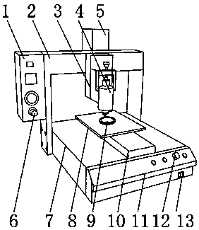
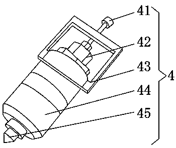
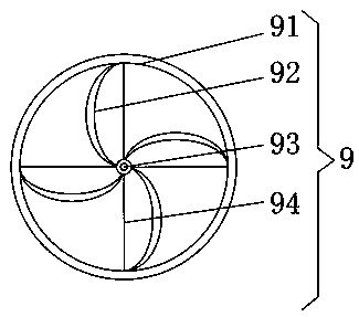
[0022] like Figure 1-3 As shown, an automatic dispensing and placement machine for glass cup lids includes a frame assembly 1, a switch gate 6 is provided at the lower end of the frame assembly 1, and a horizontal moving platform 2 is provided at the rear end of the frame assembly 1, and The rear end of the mobile platform 2 is provided with a control assembly 5, the front end of the horizontal mobile platform 2 is provided with a lifting mechanism 3, the front end of the lifting mechanism 3 is provided with a dispensing assembly device 4, and the lower end of the dispensing assembly device 4 is provided with a cutting edge device 9 The lower end of the cutting edge device 9 is provided with a mold plate 8, the lower end of the mold plate 8 is pr...


PUM


Abstract

The invention discloses an automatic dispensing chip mounter for a glass cup cover. The automatic dispensing chip mounter comprises a frame assembly, wherein a switching gate is arranged at the lowerend of the frame assembly; a horizontal moving table is arranged at the rear end of the frame assembly; a control assembly is arranged at the rear end of the horizontal moving table; and a lifting mechanism is arranged at the front end of the horizontal moving table. The automatic dispensing chip mounter for the glass cup cover is provided with a dispensing assembly device and a knife edge cuttingdevice, and the process of dispensing paster is fully automatic without manual participation, so that the efficiency is high, and the quality is good; glue mixing of different brands can be avoided due to the fact that a dispensing head is blocked; errors caused by manual operation can be avoided by the automatic equipment, the production efficiency and the consistency are improved to a large extent; continuous operation can be achieved without stopping, so that the production efficiency is greatly improved; through the paster with better quality, the nursing is safe and reliable; and the working efficiency is high, the operation is convenient, and the maintenance and nursing are safe and convenient.

Description

technical field [0001] The invention relates to the field of glue dispensing and patching, in particular to an automatic glue dispensing and patching machine for glass cup lids. Background technique [0002] In the 1970s, people's in-depth exploration of surface mount and devices represented the beginning of SMT technology. In the 1970s, Japan first discovered the future market value of SMT technology, and soon entered the research and development of a series of SMT products. According to Different placement methods, automatic dispensing and placement machines mainly have 4 categories: turret type, arch type, composite type and parallel structure type. Different types of placement can be selected according to different placement requirements and placement industries. Machine, has the advantages of high positioning accuracy, small backlash, low noise, high efficiency, high efficiency and reversibility, zero backlash and high rigidity, etc. The air path of the automatic dispen...

Claims


Application Information

Patent Timeline
Patent Type & Authority Applications(China)
IPC IPC(8): F16B11/00B05C5/02B05C13/02B05C11/00B05B15/50
CPCB05B15/50B05C5/0208B05C11/00B05C13/02F16B11/006
Inventor 康闯朝殷宪鑫
Owner 蚌埠亘乐家庭用品有限公司
Why Eureka
Try Eureka