

Speed reduction box for turbine fracturing
A reduction box and fracturing technology, applied in the field of turbo fracturing, can solve the problems of reducing the reliability and life of planetary gear transmission, uneven gear meshing parts, and reducing the rigidity of the planet carrier, achieving light weight, eliminating lateral force, reducing The effect of small vertical pressure
- Summary
- Abstract
- Description
- Claims
- Application Information
AI Technical Summary
Problems solved by technology
Method used
Image

Examples
Embodiment Construction
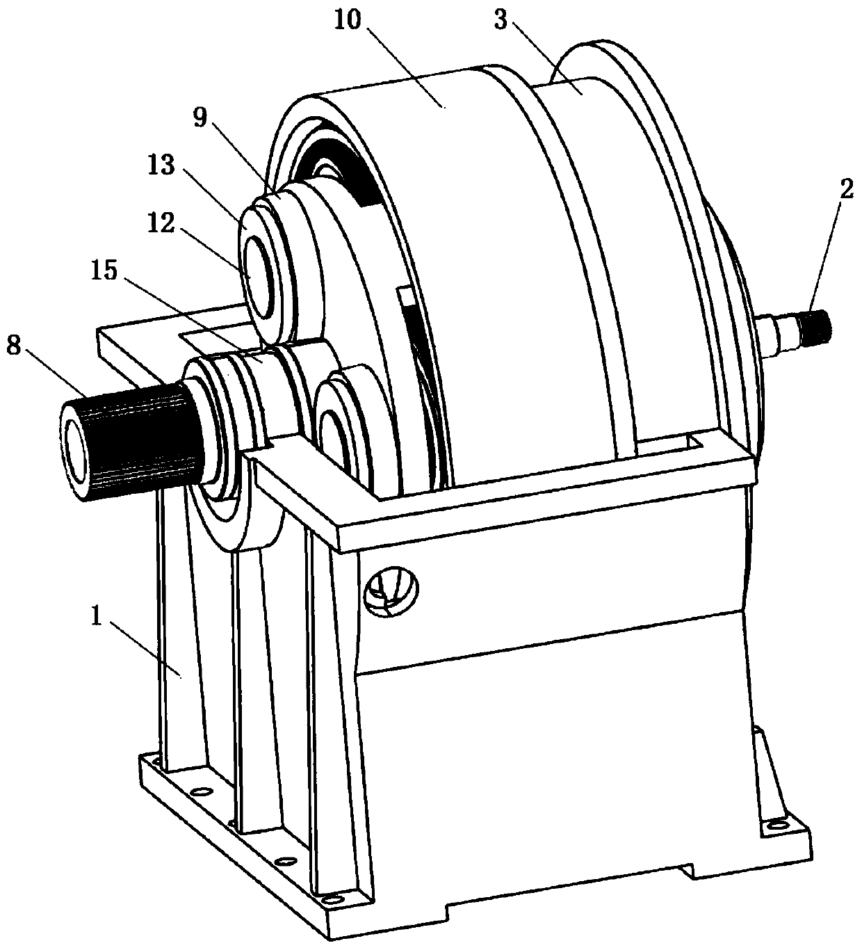
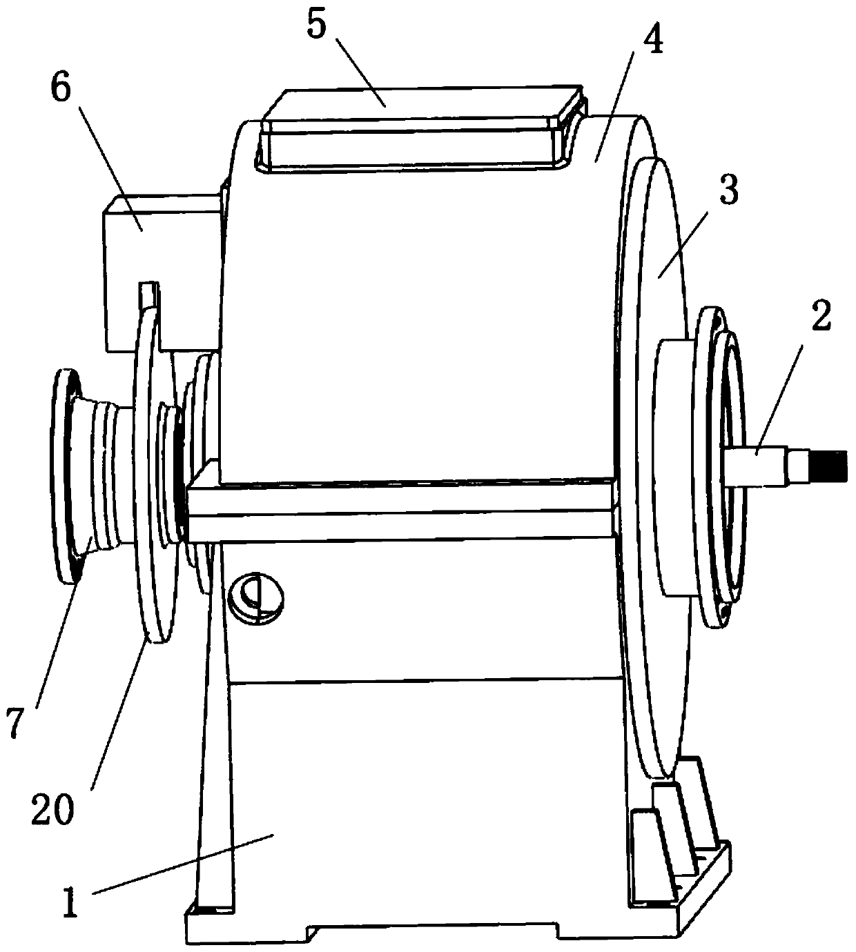
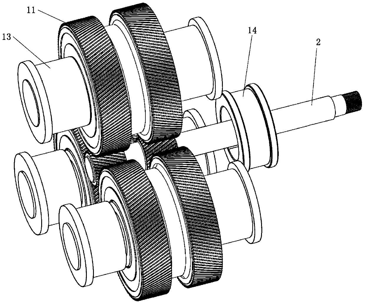
[0025] Such as Figures 1 to 6 As shown, a reduction box for turbo fracturing, the reduction box includes a sun gear shaft 2, a planetary wheel 11 and a bearing 13, the number of the planetary wheel 11 is 3, the number of the bearing 13 is 6, and the number of bearings 13 is two by two The set is used to fix a planetary gear 11, and 6 bearings 13 and 3 planetary gears 11 are respectively socketed to form 3 sets of planetary gear sets. The sun gear shaft 2 includes a large end gear and a small end gear. The 3 sets of planetary gear sets are The big end gear is distributed around it as the center of a circle, and the planetary gear 11 is meshedly connected with the big end gear. The three sets of planetary gear sets are evenly distributed around the big end gear as the center of circle. The transmission ratio of the reduction box is large, and the power is input by the small end gear of the sun gear shaft, through the engagement of the large end gear of the sun gear shaft and t...
PUM
 Abstract
Description
Claims
Application Information