
Shrub lawn trimming device for garden landscaping and using method thereof

A landscaping and lawn pruning technology, which is applied to hedge trimming equipment, botanical equipment and methods, gardening, etc., can solve the problems of easily hurting workers, no limit structure, and low pruning efficiency, so as to reduce labor intensity, Prevents direct slipping and improves cutting efficiency

Active Publication Date: 2019-11-22
马鞍山观点信息科技股份有限公司
View PDF7 Cites 4 Cited by
  • Summary
  • Abstract
  • Description
  • Claims
  • Application Information

AI Technical Summary

Problems solved by technology

[0005] The purpose of the present invention is to provide a kind of shrub and lawn trimming device for landscaping, to solve the problem of the existing landscaping shrub and lawn trimming device, the rotating disc is driven by a motor, and a cutter is arranged around the rotating disc to trim the lawn, but once The permanent trimming area is small, the trimming efficiency is low, and the workers need to swing their arms back and forth. The labor intensity of the workers is high, and the height of the trimmed lawn is inconsistent, which affects the appearance; when the trimming angle of the device cannot be trimmed, there is no limit structure, and there is a risk of the support plate slipping directly. , easy to injure workers; the angle cannot be changed arbitrarily, and when some special shapes need to be completed, specific pruning tools need to be used, the scope of application is low, and the cost of use is high; the existing pruning device support plate has no additional limit bar, no double Limiting structure, the structure is not firm, and the angle of the support plate is easy to change during work, which affects the problem of garden pruning

Method used


Image

  • Shrub lawn trimming device for garden landscaping and using method thereof
  • Shrub lawn trimming device for garden landscaping and using method thereof
  • Shrub lawn trimming device for garden landscaping and using method thereof

Examples


Embodiment Construction

[0032] The technical solutions of the present invention will be clearly and completely described below in conjunction with the embodiments. Apparently, the described embodiments are only some of the embodiments of the present invention, not all of them. Based on the embodiments of the present invention, all other embodiments obtained by persons of ordinary skill in the art without creative efforts fall within the protection scope of the present invention.

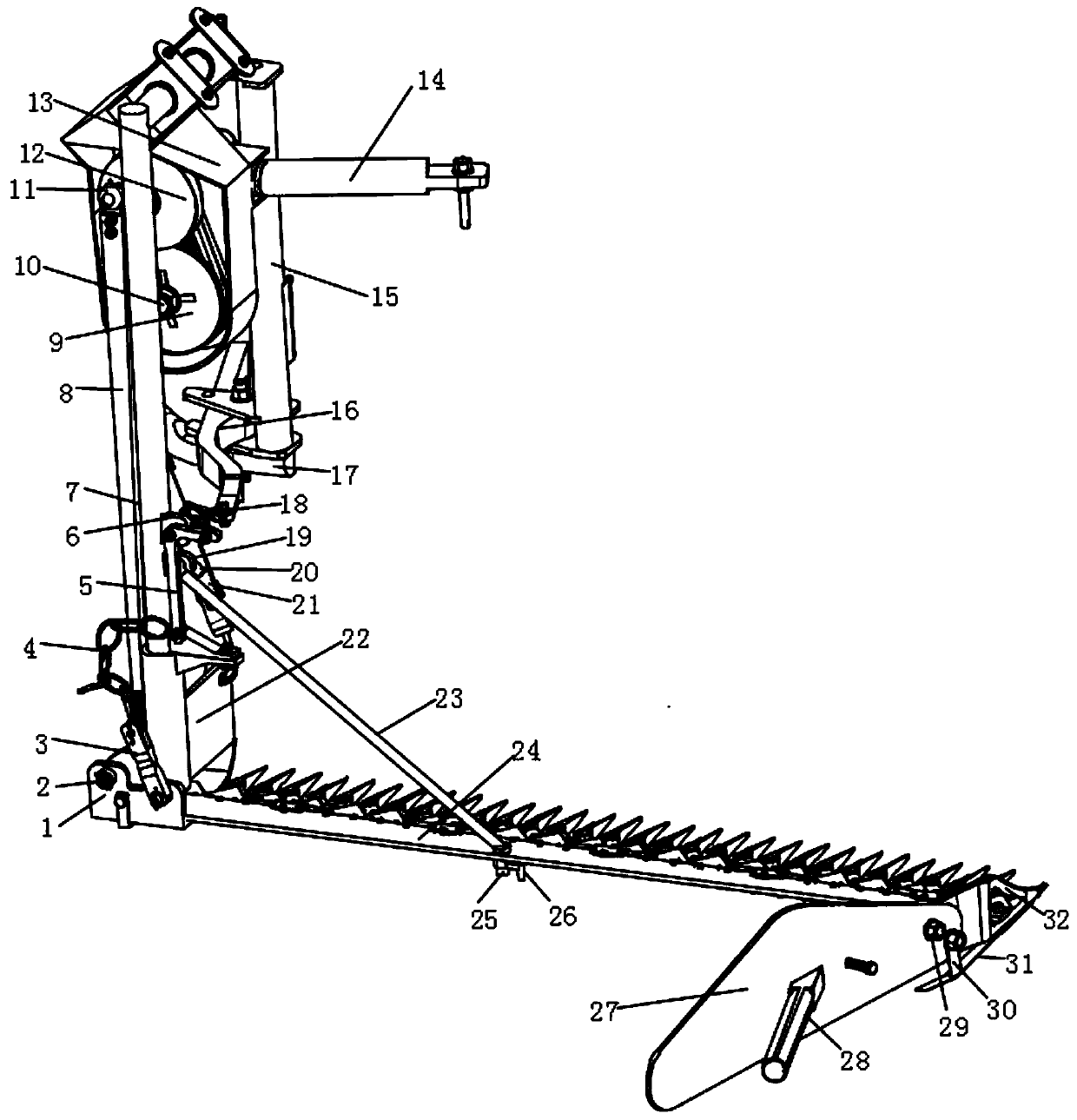
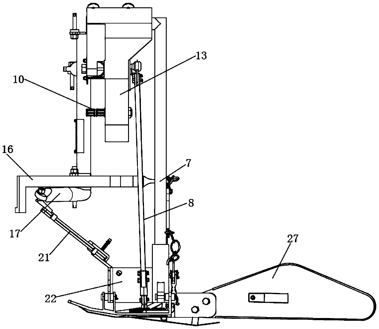
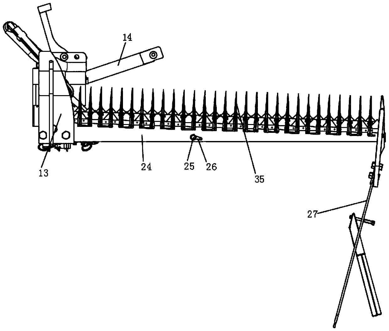
[0033] Such as Figure 1-5 Shown, a kind of shrub and lawn pruning device for landscaping, comprises that the top side of base 1 is provided with support plate 24, is provided with a row of several diverter cones 35 on the side wall of support plate 24 sides, and one end of several diverter cones 35 Fixedly arranged on the side wall of the support plate 24 and perpendicular to the side wall of the support plate 24, the middle position of each diverter cone 35 is provided with a notch, and the inside of some notches is provi...


PUM


Abstract

The invention discloses a shrub lawn trimming device for garden landscaping. A supporting plate is arranged at one side of the top of a base, a row of several flow dividing cones are arranged on the side wall of one side of the supporting plate, one ends of the flow dividing cones are fixedly arranged on the side wall of the supporting plate and are perpendicular to the side wall of the supportingplate, and a notch is formed in the middle of each flow dividing cone; the output end of a motor drives a second rotary shaft to rotate, when the second rotary shaft rotates, a driving wheel is driven to rotate, and drives a transmission wheel to rotate through a belt, and when the transmission wheel rotates, a rotation block conducts circular movement; through a transmission rod, a pulling plateis controlled to reciprocate in the notches, and several movable cutters on the pulling plate cooperate with fixed cutters to trim branches and leaves of a lawn of a garden and complete garden landscaping and trimming work. Compared with a transmission rotating-disc-type trimming device, the one-time trimming area is large, the trimming efficiency is improved, workers do not need to swing the arms back and forth, and the labor intensity of the workers is lowered.

Description

technical field [0001] The invention relates to the field of landscaping equipment, in particular to a shrub and lawn trimming device for landscaping and a method for using the same. Background technique [0002] Landscaping is the use of engineering technology and artistic means in a certain area to create a beautiful natural environment and recreational environment by transforming the terrain, planting trees and flowers, building buildings, and arranging garden roads. Shrubs and lawn pruning devices are needed for landscaping. At present, most landscaping workers use scissors or ordinary rotary lawn mowers for pruning, which is inefficient and requires a lot of labor. [0003] The Chinese patent whose publication number is CN103283377B discloses a hand-push lawn trimmer, which belongs to the technical field of gardening tools. The invention provides a hand-push lawn trimmer, which can quickly adjust the grass cutting height and the height of the push rod, and the push rod...

Claims


Application Information

Patent Timeline
IPC IPC(8): A01G3/04A01D34/13A01D34/37A01D34/40A01D75/20
CPCA01D34/13A01D34/37A01D34/40A01D75/20A01G3/04A01G3/0435A01G2003/0461
Inventor 张超左孝文王东东张弟袁紫薇
Owner 马鞍山观点信息科技股份有限公司
Learn More