Carving device for wooden door production

A technology for wooden doors and support plates, applied in wood processing appliances, forming/shaping machines, manufacturing tools, etc., can solve the problems of no positioning mechanism, pattern offset, time-consuming and labor-intensive, etc., to prevent dust flying, improve carving quality, Wide range of effects

Inactive Publication Date: 2019-11-22
百隆智能家居有限公司
View PDF10 Cites 4 Cited by
  • Summary
  • Abstract
  • Description
  • Claims
  • Application Information

AI Technical Summary

Problems solved by technology

[0003] At present, when the existing wooden door is processed by an engraving machine, the engraving machine is usually used for engraving, and the engraving machine is composed of a support frame, a support plate and an engraving mechanism, and the wooden door is placed on the support plate for engraving. During the engraving process, since there is no positioning mechanism on the suppo

Method used


Image

  • Carving device for wooden door production
  • Carving device for wooden door production
  • Carving device for wooden door production

Examples


Embodiment approach

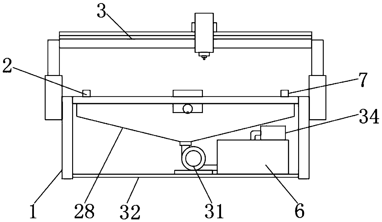
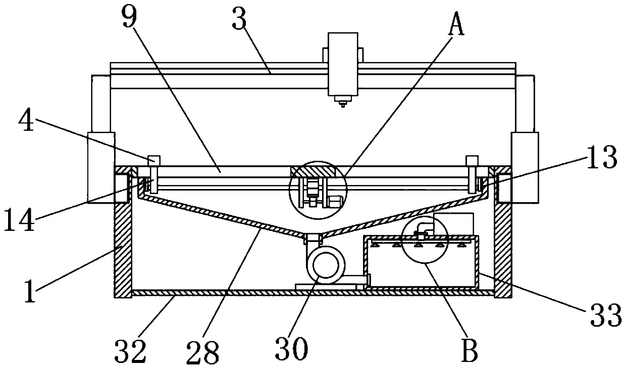
[0030] Specific embodiments: when the wooden door needs to be carved, first the wooden door is placed on the support plate 2, at this moment, the driving motor 16 runs, so that the driving rod 18 drives the driving gear 20 to rotate, and because the driving gear 20 and the driven gear 21 meshing connection, so that the driven gear 21 drives the screw rod 12 to rotate relatively on the two fixed plates 13, and the screw rod 12 used in this program is composed of two threads in opposite directions. At this time, the rotating sleeve The two moving sleeves 14 connected to the outside of the screw mandrel 12 are subjected to driving forces in two opposite directions, and because the moving sleeves 14 are sleeved on the chute 9 and under the position-limiting action of the first positioning plate 15 slidably connected to the support plate 2, Furthermore, the two moving sleeves 14 drive the two first positioning plates 15 to move towards each other, so as to achieve the effect of clam...

specific Embodiment approach

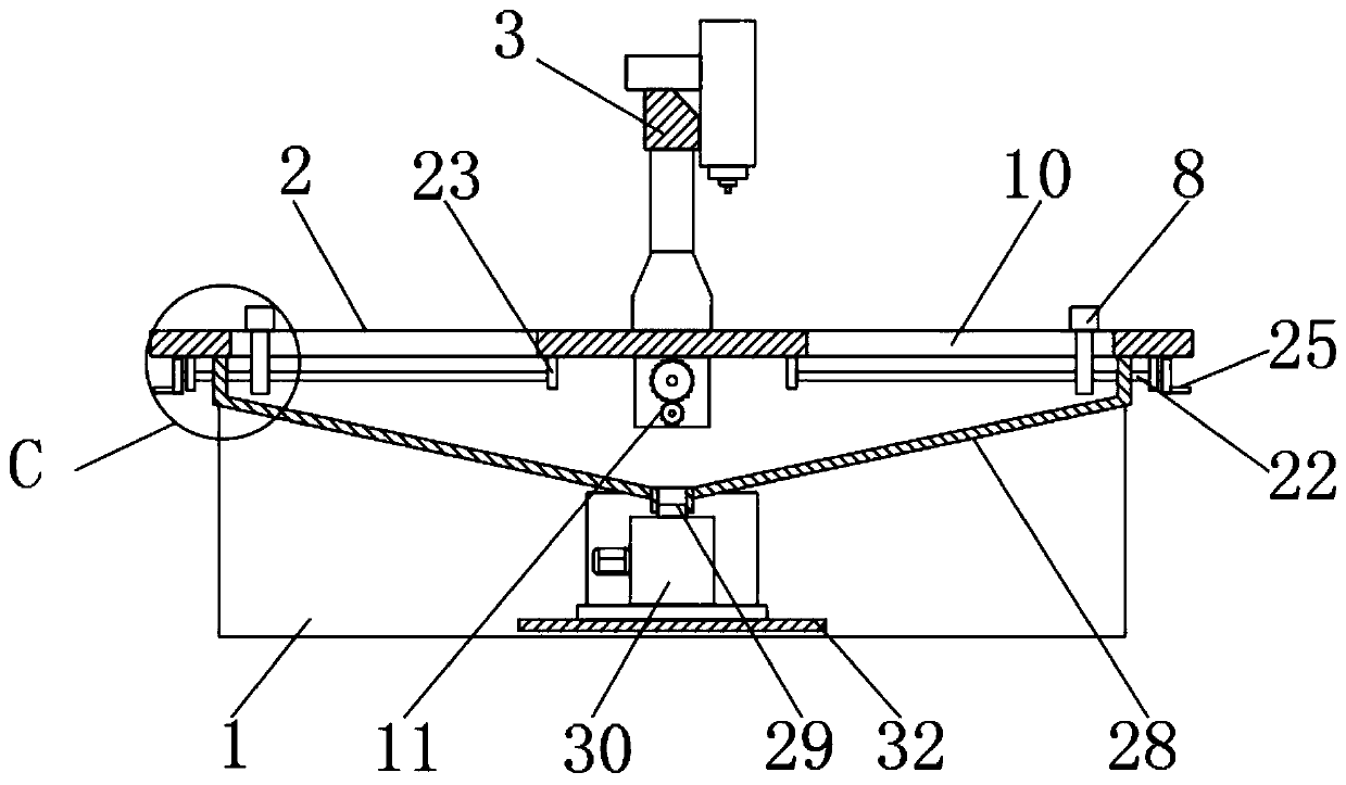
[0032] The specific embodiment: when the both sides of the wooden door are clamped, at this time, the two handles 25 relative to the other two sides of the wooden door are rotated simultaneously, and the driving force received by the handle 25 makes the threaded rod 22 relative to the first limiting plate 23 and the first limiting plate 23 respectively. The second limiting plate 24 rotates, and now the limiting sleeve 26 is driven by the threaded rod 22, and the limiting action of the limiting sleeve 26 on the limiting groove 10 and the second positioning plate 27 slidably connected on the support plate 2 Under force, the two position-limiting sleeves 26 are relatively moved on the two threaded rods 22, so as to realize the relative movement of the two second positioning plates 27 along the two position-limiting grooves 10 on the support plate 2 , so as to realize the clamping and fixing effect of the two positioning plates on the other two sides of the wooden door.

[0033] T...


PUM


Abstract

The invention discloses a carving device for wooden door production. The carving device comprises a supporting frame, a supporting plate and a carving mechanism, wherein the carving mechanism is positioned on the supporting frame; the supporting plate is fixedly connected to the top end of the supporting frame; a driving positioning device is fixedly connected to the supporting plate; a pluralityof openings are formed in the supporting plate; and an adsorption dust removal device is arranged at the bottom ends of the openings and fixedly connected to the bottom end of the supporting frame. According to the carving device for wooden door production, the driving positioning device is arranged on the supporting plate, and wooden doors are rapidly and accurately positioned by the driving positioning device when needing to be carved; and the driving positioning device is used for the wooden doors with different sizes, so that the application range is wide, and the carving quality of the wooden doors is effectively improved.

Description

technical field [0001] The invention relates to the technical field of wooden door production and processing, in particular to an engraving device for wooden door production. Background technique [0002] Wooden door engraving machine machine tool base is made of cast iron, after secondary tempering, the internal structure grains are refined, the stress is released, the gantry structure is high rigidity, the workbench is made of cast iron, which is not easy to deform, and the key joint parts are manually ground and scraped during assembly. The performance of the machine tool is stable, and it adopts precision-grade guide rails and high-precision screw rods; the interface uses international standard G codes, compatible with domestic and foreign engraving software, and the operation is simple and convenient. [0003] At present, when the existing wooden door is processed by an engraving machine, the engraving machine is usually used for engraving, and the engraving machine is ...

Claims


Application Information

Patent Timeline
IPC IPC(8): B27C5/02B27C5/06B27G3/00
CPCB27C5/02B27C5/06B27G3/00
Inventor 马西平
Owner 百隆智能家居有限公司
Why Eureka
Try Eureka