Novel prestressed pipe pile pull-out test device

A technology of prestressed pipe piles and test devices, which can be used in foundation structure tests, construction, foundation structure engineering, etc. It can solve problems such as uneven stress on bolts, slippage of outer steel plates, and damage to piles, so as to achieve stable lifting structures The effects of high stability, firm clamping of the fixture, and uniform test data

Pending Publication Date: 2019-11-22
ZHEJIANG YUANBEN TESTING TECH SERVICE
View PDF1 Cites 0 Cited by
  • Summary
  • Abstract
  • Description
  • Claims
  • Application Information

AI Technical Summary

Problems solved by technology

[0003] (1) The disadvantage of the core filling method is that concrete must be poured and welded, so it takes a lot of labor and labor for a long time to maintain, and the connection quality of the reaction force system is not easy to guarantee
[0004] (2) The disadvantage of the welding method is that the steel plate at the end of the pipe pile is easy to pull off, and it is not suitable for the test of the pullout bearing capacity of the prestressed pipe pile with a large pullout force
[0005] (3) The disadvantage of the bolt connection method is that holes are drilled on the wall of the prestressed pipe pile, causing damage to the pile body and affecting the bearing performance of the pipe pile in the later stage. Due to the brittleness of the concrete, it is difficult to accurately form the diameter of the hole, and the outer steel plate is prone to slippage. Uneven stress on each bolt

Method used


Image

  • Novel prestressed pipe pile pull-out test device
  • Novel prestressed pipe pile pull-out test device
  • Novel prestressed pipe pile pull-out test device

Examples


Embodiment Construction

[0018] The present invention will be described in further detail below in conjunction with the accompanying drawings and embodiments. The specific embodiments described therein are only used to explain the present invention, and are not intended to limit the present invention.

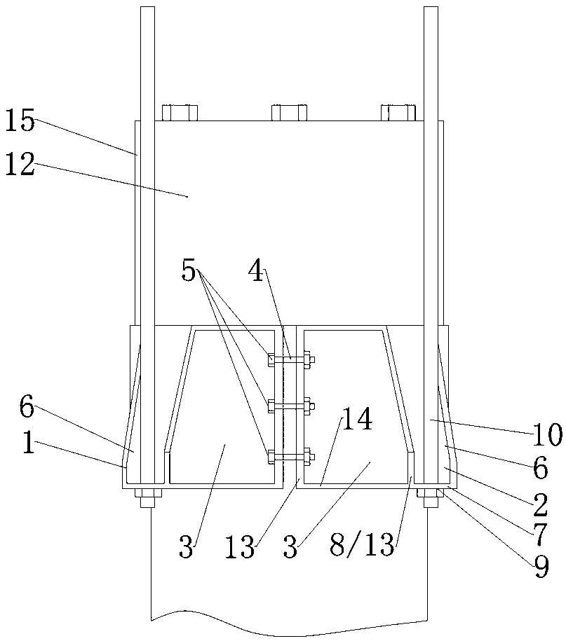
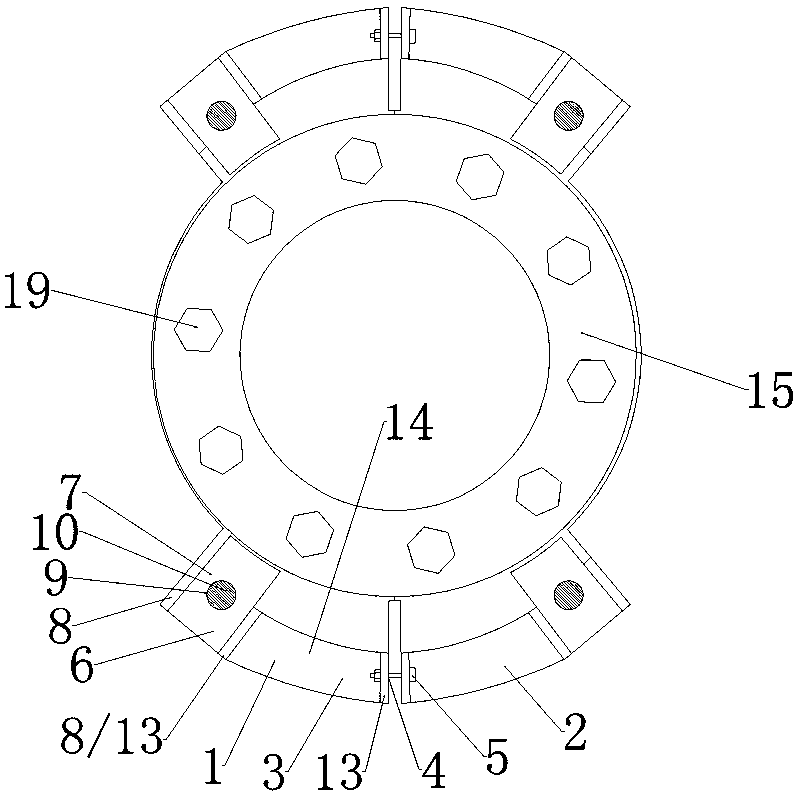
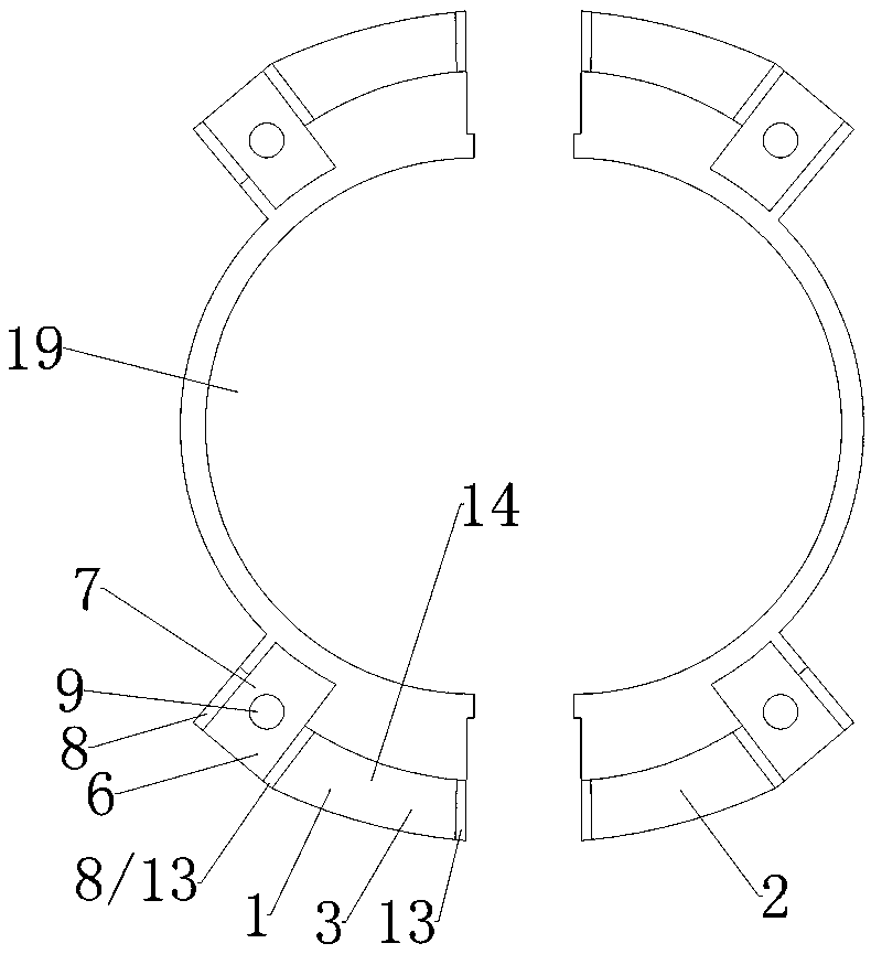
[0019] refer to Figure 1-4 As shown, the new prestressed pipe pile pull-out test device provided by the present invention includes a clamp, a clamp lifting mechanism, a tension measuring mechanism and a displacement measuring mechanism. 1 and the clamping end of the right fixture 2 have a square metal frame 3 open to the outside, and a plurality of bolt connection holes 4 are opened on the adjacent side walls of the square metal frame 3 oppositely arranged on the left fixture 1 and the right fixture 2 , the bolt 5 passes through the two bolt connection holes 4 to clamp the left clamp 1 and the right clamp 2 on the pile head, the left clamp 1 and the right clamp 2 are provided with a connecting frame 6...


PUM


Abstract

The invention discloses a novel prestressed pipe pile pull-out test device which comprises a fixture, a fixture lifting mechanism, a pull force measurement mechanism and a displacement measurement mechanism. The fixture comprises split left fixture and right fixture; square-shaped metal frames with outward openings are arranged on the outer sides of the clamping ends of the left fixture and the right fixture; bolt connecting holes are formed in adjacent side walls of the square-shaped metal frames relatively arranged on the left fixture and the right fixture; bolts penetrate through the two bolt connecting holes so as to clamp the left fixture and the right fixture onto a pile head; connecting frames are arranged on the positions, close to the square-shaped metal frames, on the left fixture and the right fixture; each connecting frame is provided with a bottom plate and side plates located at two side ends of the bottom plate; the bottom plate and the two side plates of each connectingframe are fixed onto the outer side wall of the left fixture or the right fixture; through holes are formed in the bottom plates; pull rods with external threads at the end parts penetrate through the through holes so as to be in threaded connection with nuts; and the four pull rods are jointly and symmetrically arranged on the left fixture and the right fixture. According to the device, the fixtures are firm in structure, a pull force applied to a pile body is uniform, and the fixtures are convenient to clamp.

Description

technical field [0001] The invention relates to a novel prestressed pipe pile pullout test device. Background technique [0002] There are three methods for connecting the pile body and the jack in the existing prestressed concrete pipe pile pull-out test. The first is the core filling method, which pours micro-expansion concrete in the pipe hole of the pipe pile and inserts several steel bars into the concrete. After the concrete curing reaches the design strength, the steel bars or steel bars are connected together by welding to form a counter force. Connect the system. The second is the welding method, which uses the welding method to connect the steel plate at the end of the pipe pile with the transition steel plate or the transition steel box to form a reaction force connection system. Holes are drilled, and the steel plates on the outside of the piles are connected with the pipe piles through bolts to form a reaction force connection system. The fourth is the hoop-t...

Claims


Application Information

Patent Timeline
IPC IPC(8): E02D33/00
CPCE02D33/00
Inventor 盛尔迈邵赛博
Owner ZHEJIANG YUANBEN TESTING TECH SERVICE
Why Eureka
Try Eureka