Supercharge Your Innovation With Domain-Expert AI Agents!

A tunnel advance support type locking foot anchor structure and its construction method

A technology of locking foot bolts and advanced support, which is applied to the installation of bolts, earthwork drilling, mining equipment, etc., and can solve the problems that the welding position of the end of the bolt exceeds, cannot meet the support requirements, and the welding labor intensity is high. , to achieve the effect of eliminating harmful gases, simple structure and low cost

Active Publication Date: 2020-11-27
NO 4 ENG CO LTD OF CHINA RAILWAY 11 BUREAU GRP +1
View PDF6 Cites 0 Cited by
  • Summary
  • Abstract
  • Description
  • Claims
  • Application Information

AI Technical Summary

Problems solved by technology

[0003] In actual construction, the lock-foot anchor rod and the upper section steel arch frame are welded together to form a joint bearing mechanism of the lock-foot anchor rod and the steel arch frame to jointly bear the surrounding rock pressure; however, when this connection method bears a certain surrounding rock pressure, Usually when the anchor bolt and the steel arch itself have not reached the ultimate bearing capacity, the welded part of the end of the anchor exceeds the welding strength and is prone to damage
At the same time, during the construction process, the welding labor intensity is high; and due to the limited space in the tunnel, the harmful gas generated by welding will cause certain injuries to the construction personnel.
In addition, in the cross-section of the tunnel, the traditional construction method of driving the locking foot bolt obliquely downward at the arch foot can only provide advanced support for the lower excavation, but does not provide advanced support for the front excavation. , cannot meet the support requirements

Method used


Image

  • A tunnel advance support type locking foot anchor structure and its construction method
  • A tunnel advance support type locking foot anchor structure and its construction method
  • A tunnel advance support type locking foot anchor structure and its construction method

Examples


Embodiment Construction

[0029] The present invention will be further described in detail below in conjunction with the accompanying drawings and specific embodiments.

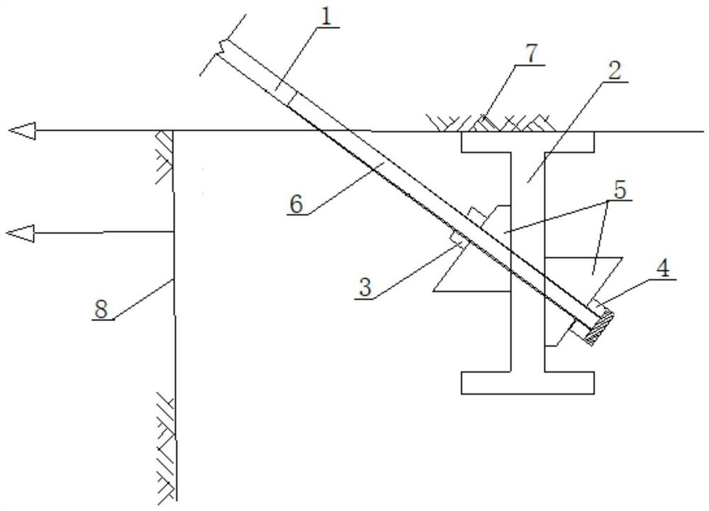
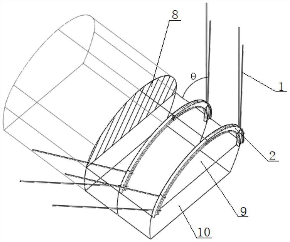
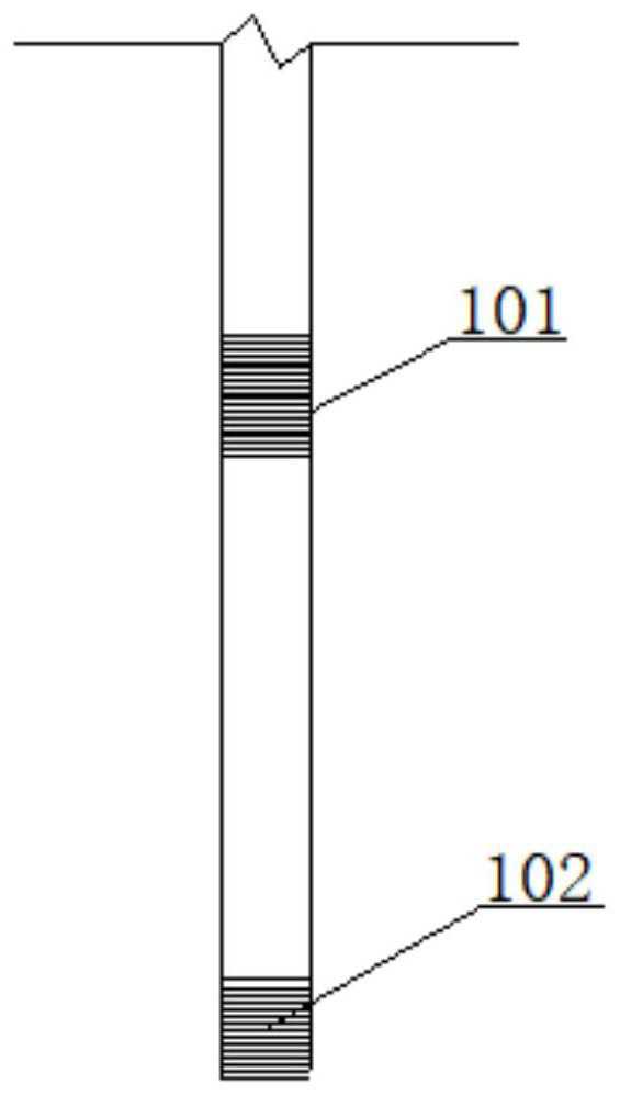
[0030] see Figure 1 to Figure 4 , a tunnel advance support type locking foot anchor structure, comprising a locking foot anchor 1 and an upper section steel arch 2. The upper profiled steel arch 2 includes flanges 201 at both ends and a web 202 in the middle, the web 202 is provided with several reserved holes 203, and the surrounding rock is provided with a plurality of drill holes corresponding to the reserved holes 203. hole, the radius of the reserved hole 203 is slightly larger than that of the locking foot bolt 1, and the locking foot bolt 1 is inserted into the corresponding drill hole through the top of the reserved hole 203; 2 before layout.

[0031] see Figure 1 to Figure 4 Specifically, the reserved holes 203 on the web 202 are arranged at a distance of 0.6m-0.8m, that is, one is arranged every 0.6m-0.8m.

[0032] see...


PUM


Abstract

The invention discloses a tunnel advance support type foot lock anchor rod structure and a construction method thereof. According to the tunnel advance support type foot lock anchor rod structure, foot lock anchor rods (1) penetrate through the tops of preformed holes (203) of upper profile steel arch frames (2) to be inserted into corresponding drilled holes, anchoring bottom plates located on the upper sides and the lower sides of the portions, penetrating through the preformed holes (203), of the foot lock anchor rods (1) fixedly abut against webs (202) through tightening anchor devices I (3) and tightening anchor devices II (4) correspondingly, and reinforcing rods (6) are inserted into the foot lock anchor rods (1). The construction method comprises the steps that surrounding rock isdrilled at first, then, the upper profile steel arch frames (2) are arranged, the drilled holes are aligned to the corresponding preformed holes (203), after the foot lock anchor rods (1) are insertedinto the drilled holes of the surrounding rock, and the tightening anchor devices I (3) are tightened, grout permeates and diffuses into holes or fractures of the rock stratum through the foot lock anchor rods (1) with assistance of pressure of a grouting pump, and finally, the reinforcing rods (6) are inserted into the foot lock anchor rods (1). The self-stabilization capacity of the tunnel surrounding rock is greatly improved, and the advance support effect is good.

Description

technical field [0001] The invention relates to a concrete pouring device, more specifically to a tunnel advance support type locking foot anchor structure and a construction method thereof, belonging to the technical field of tunnel construction. Background technique [0002] With the vigorous development of highway and railway tunnels in our country, the proportion of tunnels is increasing day by day; in the construction of tunnel engineering, more and more tunnel safety support problems are encountered, so ensuring the stability of tunnel surrounding rock is of great significance to tunnel construction. Lock foot bolt is to press the bolt into the stratum in the steel grid or section steel through drilling, and the grout will infiltrate and diffuse into the pores or cracks of the rock through the pressure of the grouting pump to improve the physical mechanics of the rock mass. It can effectively limit the relaxation and deformation of the rock formation, thereby achieving...

Claims


Application Information

Patent Timeline
Patent Type & Authority Patents(China)
IPC IPC(8): E21D21/00
CPCE21D21/0026E21D21/008E21D21/0093
Inventor 王更峰王力张克宏张晓晓王兴留王桂林梁锋孙帆张亮刘勃龙毕靖
Owner NO 4 ENG CO LTD OF CHINA RAILWAY 11 BUREAU GRP
Features
  • R&D
  • Intellectual Property
  • Life Sciences
  • Materials
  • Tech Scout
  • Unparalleled Data Quality
  • Higher Quality Content
  • 60% Fewer Hallucinations
Learn More