
A liquid metal pouring melt sampling and analysis device

A technology of sampling analysis and liquid metal, which is applied in the field of metal processing, can solve the problems of high-temperature burns on the operator's hand and high heat of the sampling cylinder, and achieve the effect of improving the ease of operation and sealing

Active Publication Date: 2020-05-15
江西鑫航精密铸造有限公司
View PDF9 Cites 0 Cited by
  • Summary
  • Abstract
  • Description
  • Claims
  • Application Information

AI Technical Summary

Problems solved by technology

[0007] In view of the problems in the prior art, the object of the present invention is to provide a liquid metal pouring melt sampling and analysis device to solve the problem that when the sampling cylinder penetrates into the liquid metal to scoop up the metal solution, it needs to be inclined at a certain angle to scoop the solution into the In the sampling cylinder and when the sampling cylinder is lifted upwards from the metal solution, the heat on the top of the sampling cylinder is too high, which is likely to cause high-temperature burns to the operator's hands.

Method used


Image

  • A liquid metal pouring melt sampling and analysis device
  • A liquid metal pouring melt sampling and analysis device
  • A liquid metal pouring melt sampling and analysis device

Examples


Embodiment 1

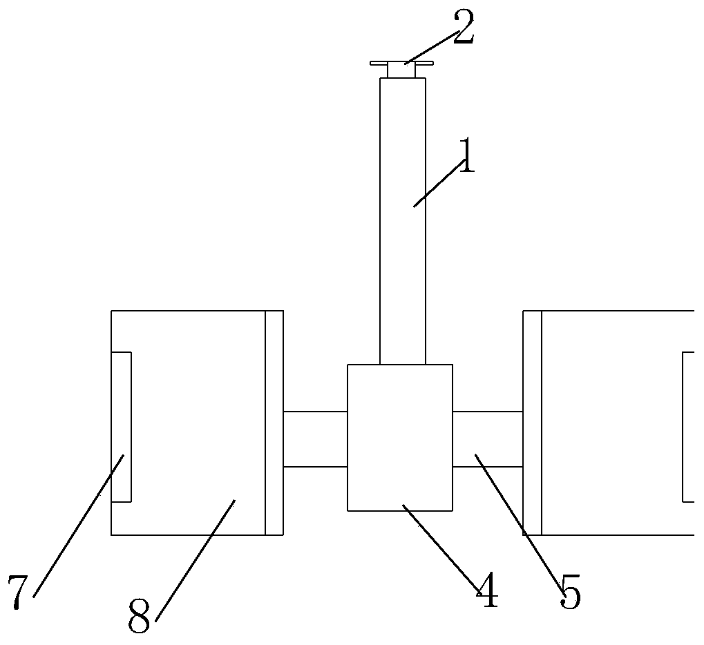
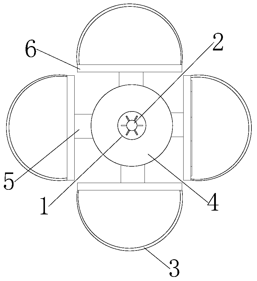
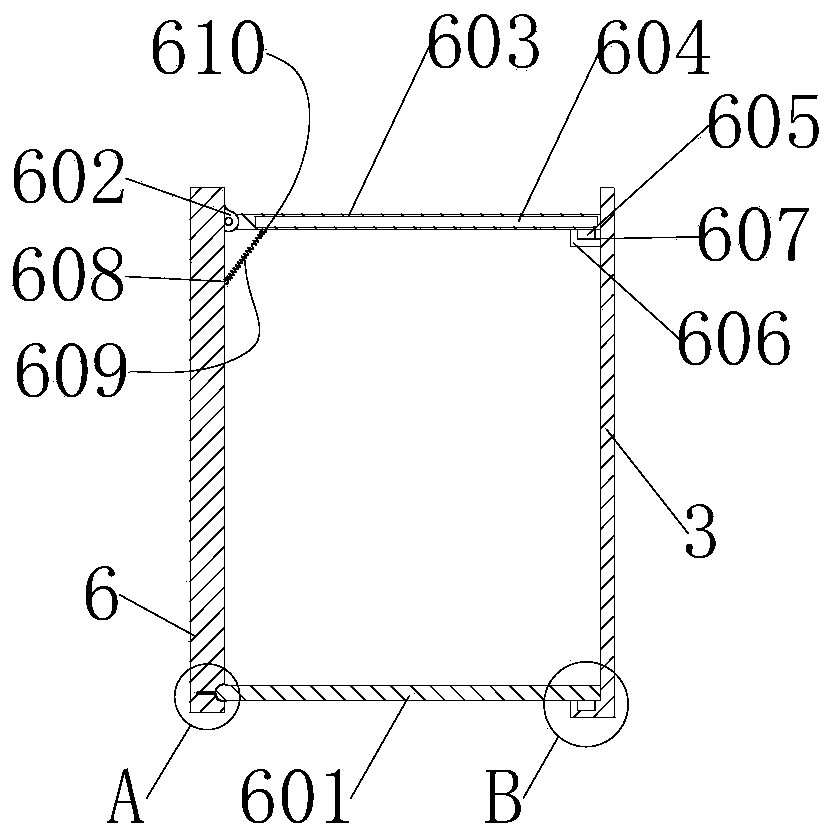
[0038] see Figure 1-6, is a schematic diagram of the overall structure of a liquid metal pouring melt sampling and analysis device, including a central cylinder 4, the central cylinder 4 is set in a cylindrical shape, the top of the central cylinder 4 is provided with an upright lifting rod 1, and the top axis of the lifting rod 1 is Pulling rods 2 are installed at the position, and hanging rods 5 are installed at equal intervals on the outer surface of the central cylinder 4. The hanging rods 5 are perpendicular to the carrying rod 1. The top of each hanging rod 5 is fixed with a sampling cylinder 8, and the outer wall of the sampling cylinder 8 Observation window 7 is arranged, and the middle of observation window 7 is provided with high-temperature-resistant transparent glass, and the material that this high-temperature-resistant glass uses is No. 4 material glass, and the glass of No. 4 material is below 1200 degrees.

[0039] The sampling cylinder 8 includes a straight p...

Embodiment 2

[0052] see Figure 1-7 , is a schematic diagram of the overall structure of a liquid metal casting melt sampling and analysis device. This embodiment has the same content as the above-mentioned embodiment 1, and the same will not be described in this embodiment. The specific differences are:

[0053] A circular hole 401 is arranged inside the central cylinder 4, and a hollow structure support column 402 is provided at the axial center of the bottom end of the circular hole 401. The top of the support column 402 is provided with a snap-in groove, and the top of the support column is provided with equidistantly distributed The clamping groove is set as a U-shaped groove with the opening facing upwards. The outer wall of the central cylinder 4 is provided with square holes 404 at equal intervals. The square holes 404 and the circular holes 401 are connected. There are two symmetrically distributed sliding holes 403, wherein the top of each square hole 404 has the same height, and...


PUM


Abstract

The invention discloses a liquid metal pouring melt sampling and analyzing device, which relates to the technical field of metal processing, and comprises a central cylinder, wherein a vertical lifting rod is arranged at the top end of the central cylinder, a shifting rod is arranged at the axis position of the top end of the lifting rod, hanging rods are arranged on the outer circular surface ofthe central cylinder at equal intervals, the hanging rods are perpendicular to the lifting rod, and a sampling cylinder is fixed at the top end of each hanging rod; and each sampling cylinder comprises a straight plate and an arc-shaped plate, each sampling cylinder is formed by connecting the straight plate of a square structure and the arc-shaped plate of a semicircular structure, and the upperand lower ends of the sampling cylinder formed by splicing are communicated. The upper end and the lower end of the sampling cylinder are communicated, hinge bases are installed at the top ends of thestraight plates, the hinge bases are hinged with a top sealing plate, the bottom part of the top sealing plate is provided with a tension spring for pulling, so that the top sealing plate is automatically buckled under the tension of the tension spring when the sampling cylinders are lifted upwards from a metallic solution, thereby avoiding an arm holding the lifting rod from being burnt by temperature in the sampling cylinder.

Description

technical field [0001] The invention relates to the technical field of metal processing, in particular to a liquid metal pouring melt sampling and analyzing device. Background technique [0002] Liquid metal refers to a kind of amorphous metal. Liquid metal can be regarded as a mixture composed of positive ion fluid and free electron gas; liquid metal is also a kind of amorphous, flowable liquid metal. The forming process and control of liquid metal, the hydraulic characteristics and flow conditions of the filling process of liquid metal The filling process has a great impact on the quality of castings Various defects that may be caused, such as cold shut, insufficient pouring, inclusions, pores, sand inclusions, Defects such as sticky sand are all produced when the liquid metal filling is unfavorable. The correct design of the gating system makes the liquid metal fill the cavity smoothly and reasonably, which plays a very important role in ensuring the quality of the casti...

Claims


Application Information

Patent Timeline
Patent Type & Authority Patents(China)
IPC IPC(8): G01N1/10G01N33/205
CPCG01N1/10G01N33/205
Inventor 倪枫荷胡峰
Owner 江西鑫航精密铸造有限公司
Learn More