A mobile robot and its working method
A mobile, robotic technology, applied in the field of robotics, can solve the problems of increasing the weight of the robot, unable to carry path planning, and high requirements for driving motors, and achieves the effects of high cost, simplified structure, variable number of components and degrees of freedom
- Summary
- Abstract
- Description
- Claims
- Application Information
AI Technical Summary
Problems solved by technology
Method used
Image
Examples
Embodiment 1
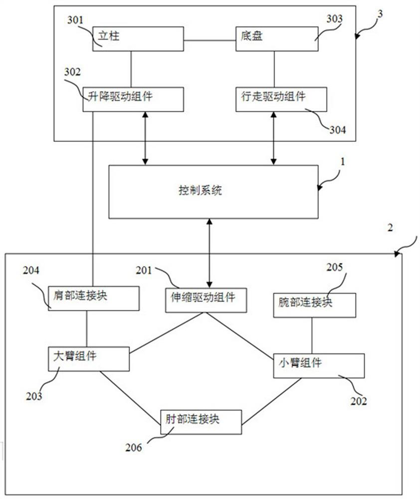
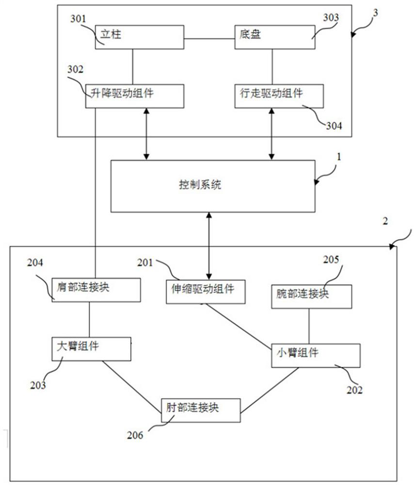
[0049] refer to figure 1 , this figure is a structural block diagram of the robot of the present invention, including a control system 1 for receiving information, and controlling the mobile lifting column 3 and the mechanism type telescopic arm 2 according to the information and control algorithm; the mobile lifting column 3, according to the carrying path of the target item According to the instructions of the control system, the movement and / or zero-radius rotation are realized; the mechanism type telescopic arm 2 is slidably connected with the mobile lifting column 3 through the shoulder connection block 204, and completes the vertical lifting movement according to the instructions of the control system, and then Under the control of the control system, the telescopic movement in the horizontal direction is performed through the telescopic movement of the mechanism arm.
[0050] Specifically, the mechanism-type telescopic arm includes a large arm assembly 203 and a small a...
Embodiment 2
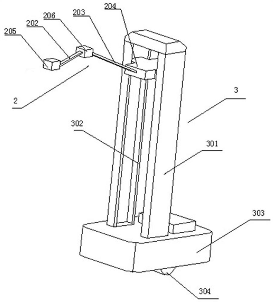
[0062] refer to image 3 , which is a structural schematic diagram of an embodiment of the robot of the present invention, the robot includes a mechanism-type telescopic arm 2 and a moving lifting column 3, and the moving lifting column 3 is connected to the mechanism-type telescopic arm 2. Mechanism type telescopic arm 2 comprises big arm assembly 203, small arm assembly 202, shoulder connecting block 204, elbow connecting block 206 and wrist connecting block 205; The other end of arm assembly 203 is rotatably connected to elbow connecting block 206 ; one end of forearm assembly 202 is rotatably connected to elbow connecting block 206 , and the other end of forearm assembly 202 is rotatably connected to wrist connecting block 205 . The mobile lifting column 3 includes a column 301 , a lifting drive assembly 302 and a chassis 303 , the column 301 is fixedly mounted on the chassis 303 , and the lifting drive assembly 302 is slidably installed inside the column 301 . The contro...
Embodiment 3
[0064] refer to Figure 4 , is a structural schematic diagram of a mechanical telescopic arm of the robot of the present invention. The large arm assembly 203, the shoulder connecting block 204, and the elbow connecting block 206 form a parallelogram through rotational connection, and the two sides of the large arm assembly 203 in the parallelogram Relatively movable; the forearm assembly 202, the elbow connecting block 206, and the wrist connecting block 205 form a parallelogram through rotational connections, and the two sides of the forearm assembly 202 in the parallelogram can move relatively. The telescopic driving assembly 201 is composed of a first driving rod 2012, a second driving rod 2013 and a driving block 2011. The first driving rod 2012, the second driving rod 2013, the boom assembly 203, the small arm assembly 202 and the driving block 2011 are connected by rotation Constructing a parallelogram, the driving block 2011 is slidably connected to the shoulder connec...
PUM
 Abstract
Description
Claims
Application Information
 - R&D
- Intellectual Property
- Life Sciences
- Materials
- Tech Scout
- Unparalleled Data Quality
- Higher Quality Content
- 60% Fewer Hallucinations
Browse by: Latest US Patents, China's latest patents, Technical Efficacy Thesaurus, Application Domain, Technology Topic, Popular Technical Reports.
© 2025 PatSnap. All rights reserved.Legal|Privacy policy|Modern Slavery Act Transparency Statement|Sitemap|About US| Contact US: help@patsnap.com


