
New energy automobile low-voltage power supply system and control method thereof

A new energy vehicle and power supply system technology, applied in electric vehicle charging technology, battery/fuel cell control devices, electric vehicles, etc., can solve problems such as unfavorable vehicle weight reduction, increased vehicle cost, and battery pack damage. Achieve the effect of facilitating the layout of the power system, improving the battery life of the whole vehicle, and reducing the cost of the whole vehicle

Pending Publication Date: 2019-11-26
ANHUI UNIVERSITY OF TECHNOLOGY AND SCIENCE
View PDF5 Cites 10 Cited by
  • Summary
  • Abstract
  • Description
  • Claims
  • Application Information

AI Technical Summary

Problems solved by technology

[0005] 1. The battery cost is high, which increases the cost of the vehicle
[0006] 2. The quality of the battery is heavy, because the curb quality of the whole vehicle has a great relationship with the fuel consumption and power consumption of the whole vehicle, which is not conducive to the lightweight of the whole vehicle
[0007] 3. The battery is large in size and takes up a lot of space in the vehicle, which is not conducive to the layout of the power system
[0008] 4. The whole vehicle is powered by a battery. The battery generally uses a lead battery, which has a short life and is easily damaged by over-discharge if it is not charged for a long time.
[0009] In view of the above problems, DCDC can be used to replace the battery power supply. DCDC takes the high-voltage power of the battery pack and converts it into low-voltage power to supply power for the whole vehicle. However, directly taking the high-voltage power of the battery pack will easily cause the SOC of the battery pack to be too low, and long-term storage of the vehicle will easily cause The ground of the battery pack is damaged

Method used


Image

  • New energy automobile low-voltage power supply system and control method thereof

Examples


Embodiment Construction

[0034] Referring to the accompanying drawings, through the description of the embodiments, the specific embodiments of the present invention include the shape, structure, mutual position and connection relationship of each part, the function and working principle of each part, and the manufacturing process of the various components involved. And the method of operation and use, etc., are described in further detail to help those skilled in the art have a more complete, accurate and in-depth understanding of the inventive concepts and technical solutions of the present invention.

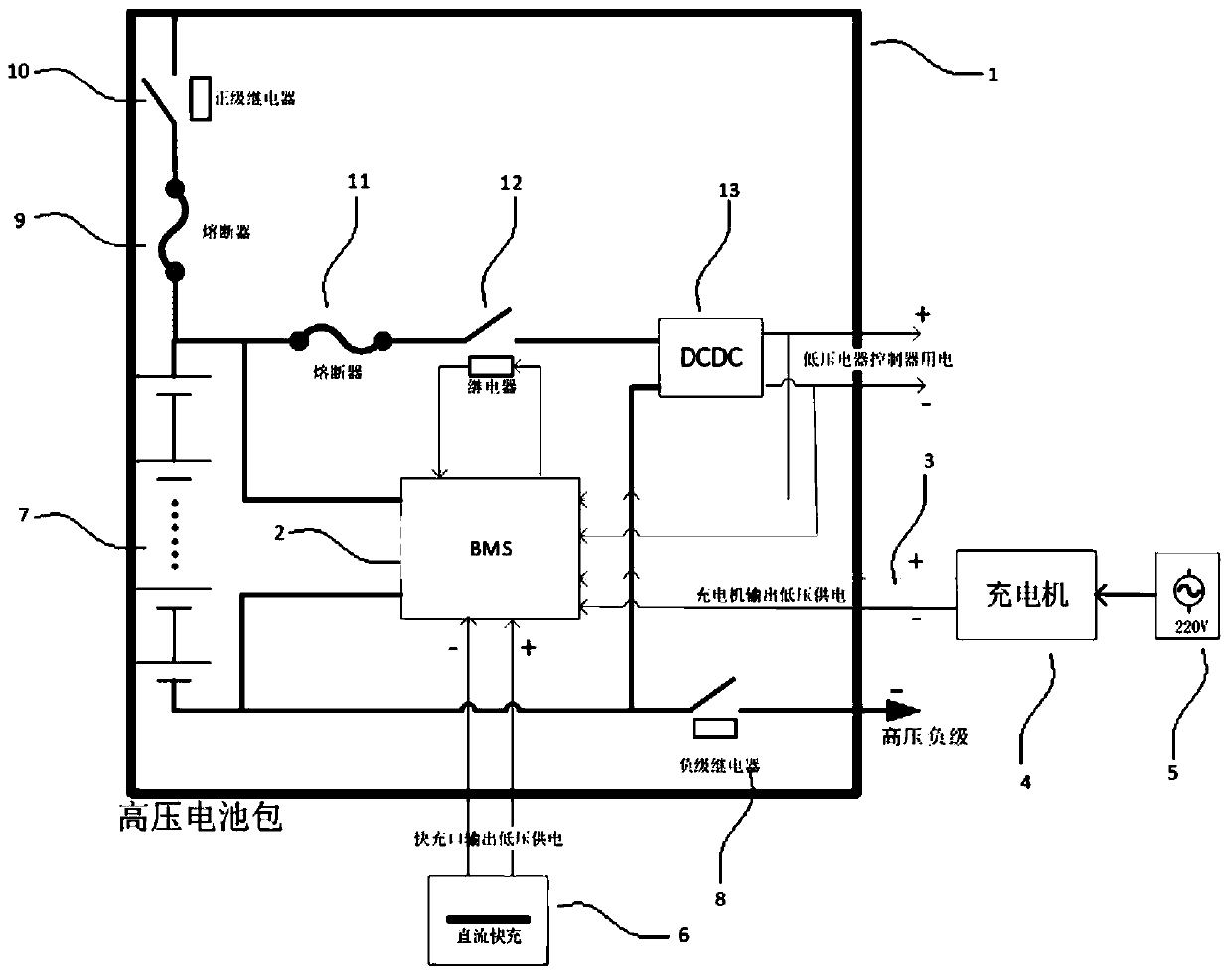
[0035] Such as figure 1 As shown, the low-voltage power supply system of new energy vehicles includes high-voltage battery pack 1, battery management system 2 (BMS), charger 4, charging gun 5, DC fast charging 6, battery pack 7, negative relay 8, and positive fuse 9 , Positive relay 10, DCDC fuse 11, DCDC relay 12, DCDC13 (high voltage DC to low voltage DC).

[0036] A battery pack 7 , a negative re...


PUM


Abstract

The invention discloses a new energy automobile low-voltage power supply system. According to the new energy automobile low-voltage power supply system, a new energy automobile is provided with a battery pack taken as a power energy source, two poles of the battery pack are connected with a battery management system, the battery management system is provided with a slow charging interface connected with a battery charger and a quick charging interface connected with direct current quick charging equipment, the two poles of the battery pack are connected with the input end of a DCDC (Direct Current Direct Current Converter), the low-voltage output end of the DCDC is directly connected with vehicle-mounted electrical devices, a DCDC fuse cutout and a DCDC relay are connected in series between the positive pole of the battery pack and the DCDC, and a relay control interface of the battery management system is connected with an input end circuit of the DCDC relay. By means of the new energy automobile low-voltage power supply system, low-voltage power supply is solved, the full vehicle cost is reduced, and the problems of too low battery pack electric quantity and battery overdischarging in the DCDC continuous power supply process are also solved.

Description

technical field [0001] The invention relates to the field of new energy vehicles. Background technique [0002] At present, whether the new energy vehicle is an electric vehicle or a hybrid vehicle without wheels, the power supply of the low-voltage electrical appliance controller is 12V / 24V, and the power supply scheme is used to charge the vehicle battery after the high-voltage battery pack is transformed by DCDC (high-voltage direct current to low-voltage direct current). . The on-board battery supplies power to low-voltage electrical equipment. [0003] Because traditional fuel vehicles do not have high-voltage battery packs, the electrical equipment of the vehicle must use the engine to drive a small motor to generate electricity to charge the battery. Moreover, when starting a traditional fuel vehicle, the starter needs to drive the internal combustion engine to start, so a large peak power is required. Therefore, a low-voltage battery is required to store electrici...

Claims


Application Information

Patent Timeline
Patent Type & Authority Applications(China)
IPC IPC(8): B60L1/00B60L58/10B60L58/14B60L3/00B60L3/04B60Q9/00B60L53/20
CPCB60L1/00B60L58/10B60L58/14B60L3/0046B60L3/04B60Q9/00B60L53/20Y02T10/70Y02T90/14Y02T10/7072
Inventor 刘贵如刘志军王陆林候凤妮
Owner ANHUI UNIVERSITY OF TECHNOLOGY AND SCIENCE
Learn More