Check patentability & draft patents in minutes with Patsnap Eureka AI!

Micro-power-consumption low-voltage detection circuit for MCU

A low-voltage detection and micro-power consumption technology, which is applied in the directions of only measuring voltage, error detection/correction, measuring current/voltage, etc., can solve the problems of large power consumption, large working current, and cannot meet the static power consumption of MCU, and achieve Low power consumption, compact circuit structure, easy to popularize and popularize

Active Publication Date: 2019-11-26
SHANGHAI CHIPON MICRO ELECTRONICS CO LTD
View PDF10 Cites 2 Cited by
  • Summary
  • Abstract
  • Description
  • Claims
  • Application Information

AI Technical Summary

Problems solved by technology

[0006] The invention provides a micro-power consumption low-voltage detection circuit for MCU, which solves the problems that the existing low-voltage detection circuit has relatively large operating current, large power consumption, and cannot meet the static power consumption requirements of the MCU.

Method used


Image

  • Micro-power-consumption low-voltage detection circuit for MCU
  • Micro-power-consumption low-voltage detection circuit for MCU
  • Micro-power-consumption low-voltage detection circuit for MCU

Examples


Embodiment Construction

[0023] Specific embodiments of the present invention will be described in further detail below in conjunction with the accompanying drawings.

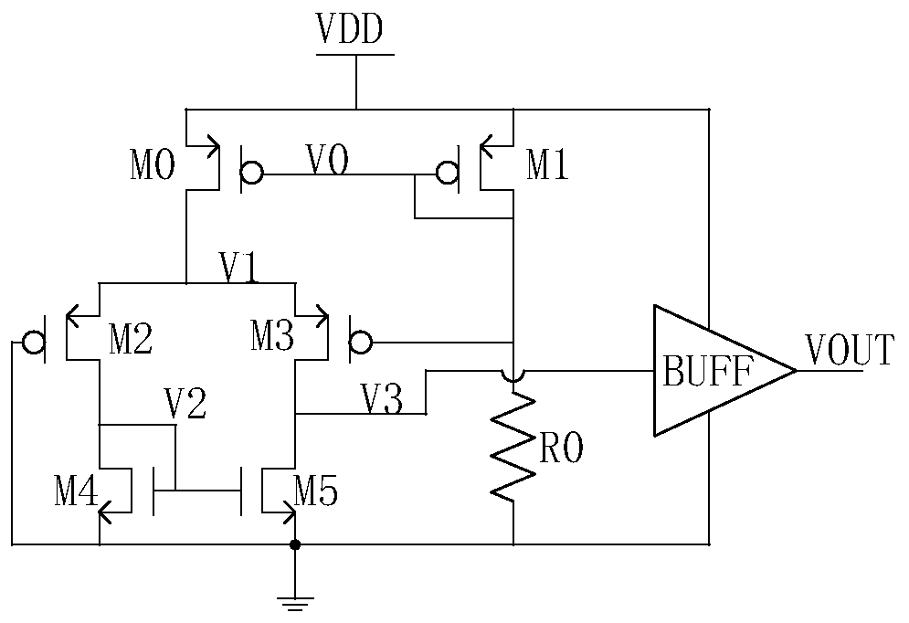
[0024] Refer to attached figure 1 , the present invention provides a micro-power consumption low-voltage detection circuit for MCU, which is used for low-voltage detection in MCU power-on and power-off processes, including a mirror current module, the input terminal of the mirror current module is connected to the MCU power supply voltage The output end is connected to the input end of the comparison module and one end of the ballast resistor, the input end of the comparison module is also connected to one end of the ballast resistor, and the output end is connected to one end of the load and the shaping module. The other end of the ground. The mirror current module is used to generate a pair of mirror currents that change with the change of the MCU supply voltage, which respectively flow through the comparison module and the ballast ...


PUM


Abstract

The invention, which relates to the technical field of detection circuits, discloses a micro-power-consumption low-voltage detection circuit for an MCU, thereby realizing low-voltage detection duringpower-on and power-down processes of the M6CU. The micro-power-consumption low-voltage detection circuit comprises a mirror image current module; the input terminal of the mirror image current moduleis connected with an MCU power supply voltage and the output terminal of the mirror image current module is connected with the input terminal of a comparison module and one end of a ballast resistor;the input terminal of the comparison module is also connected to one end of the ballast resistor and the output terminal of the comparison module is connected to one end of the load and a shaping module; and the other ends of the ballast resistor and the load are grounded. The mirror image current module is used for generating one pair of mirror image currents changing with changes of the MCU power supply voltage; and the mirror image currents flow through the comparison module and the ballast resistor respectively. The comparison module is used for carrying out overturning outputting according to the voltage on the ballast resistor and the voltage change of the mirror image current module. The shaping module is used for shaping the overturning output from the comparison module and outputting corresponding high and low levels. The micro-power-consumption low-voltage detection circuit having advantages of compact structure and great convenience in controlling is convenient to popularizeand promote.

Description

technical field [0001] The invention relates to the technical field of detection circuits, in particular to a micro-power consumption low-voltage detection circuit for an MCU. Background technique [0002] Microprocessor MCU is a complex system, including ROM, SRAM, SFR, instruction operation unit and various peripherals. In order for the system to work stably and reliably, the power supply voltage VDD must be within a certain voltage range. When the voltage is too high, the circuit will be damaged, and when the voltage is too low, the transistors will not work properly, especially the ROM, and reading errors will occur. [0003] The operating voltage range can be determined by the user, but there is a process that the user cannot control, that is, the MCU must be powered on and off. During power-on and power-off, when VDD is less than a certain voltage, the MCU must stop working, especially in some dangerous operations, such as blasting. If there is a system execution err...

Claims


Application Information

Patent Timeline
IPC IPC(8): G01R19/00G06F1/24G06F1/28G06F1/3234G06F11/30
CPCG01R19/0084G06F1/24G06F1/28G06F1/3243G06F11/3024G06F11/3058Y02D10/00
Inventor 丁晓兵常成星冯旭胡锦通朱少华
Owner SHANGHAI CHIPON MICRO ELECTRONICS CO LTD
Features
  • R&D
  • Intellectual Property
  • Life Sciences
  • Materials
  • Tech Scout
  • Unparalleled Data Quality
  • Higher Quality Content
  • 60% Fewer Hallucinations
Learn More