Tunable unidirectional crossed waveguide distributor based on PT symmetrical structure and magneto-photonic crystal
A technology of magnetophotonic crystal and symmetric structure, applied in the directions of instruments, optics, nonlinear optics, etc., can solve the problems of single signal output mode, the number of signal output channels cannot be controlled in the direction of signal output, etc., and achieve obvious effect and backscattering. Good suppression effect
- Summary
- Abstract
- Description
- Claims
- Application Information
AI Technical Summary
Problems solved by technology
Method used
Image
Examples
Embodiment 1
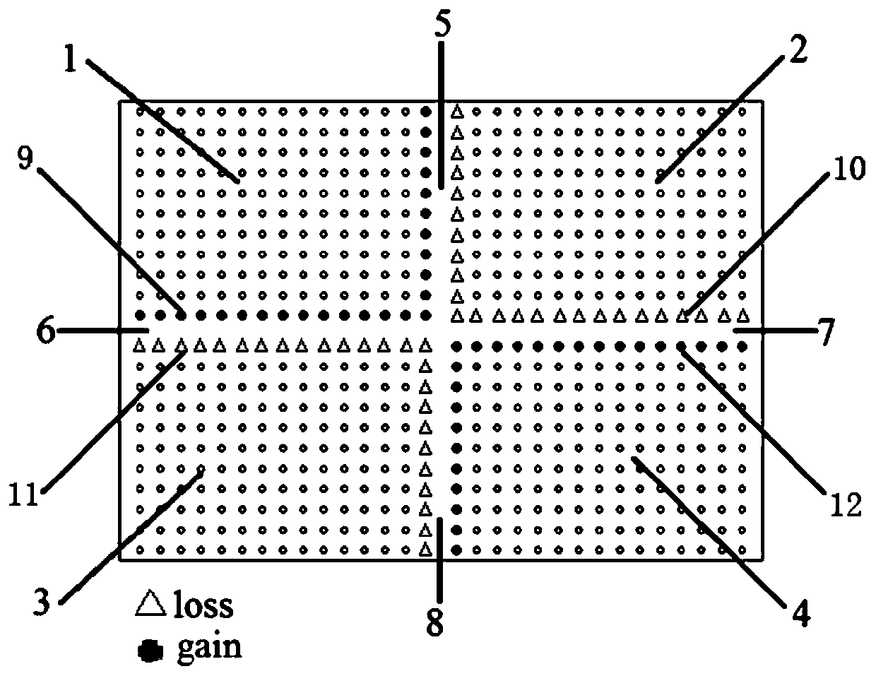
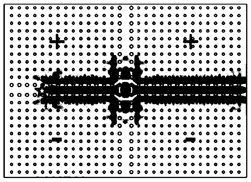
[0064] In this embodiment, the signal is input from the second channel 6, and the point source frequency is 1.25e 14 Hz, the first array 1 and the second array 2 are applied with a positive direction magnetic field, and the third array 3 and the fourth array 4 are applied with a negative direction magnetic field. The calculated steady-state electric field Ez distribution is as follows: image 3 shown. It can be seen from the figure that due to the topological protection, the signal does not disperse to the longitudinal channel when it is transmitted to the intersection of longitudinal and transverse transmission, but continues along the transverse waveguide structure and is output from the third channel 7 .
Embodiment 2
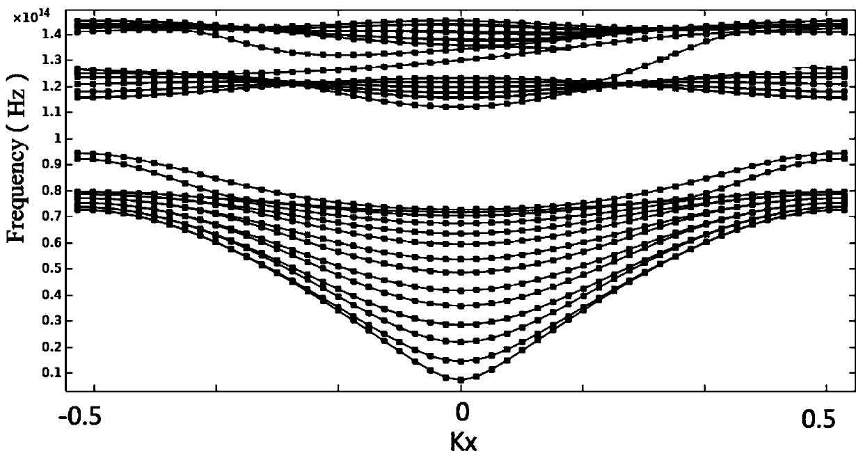
[0066] In this embodiment, the setting of the point current source and its position is the same as that of Embodiment 1, the difference is: the third array 3 is applied with a magnetic field in a negative direction, and the remaining three arrays are applied with a magnetic field in a positive direction, and the obtained electric fields are as follows: Figure 4 shown. It can be seen that since the same magnetic field corresponds to the horizontal energy band without dispersion and the opposite magnetic field corresponds to the energy band of one-way transmission, the signal can be collimated and propagated at 90 degrees, and the signal is output from the fourth channel 8, and the signal is bent spontaneously under the action of the external magnetic field L-shaped transmission. Because it is protected by topology, the backscatter suppression effect is obvious. It can be seen that there is no leakage wave in channel 1 and channel 3, and there is no signal output.
Embodiment 3
[0068] In this embodiment, the settings of the point current source and its position are the same as those in Embodiment 1, the difference is that the first array 1 is applied with a positive direction magnetic field, and the other three arrays are applied with a negative direction magnetic field. The calculated steady-state magnetic field is as follows: Figure 5 shown.
[0069] For the second channel 6, an external magnetic field of upper positive and lower negative is applied, so the signal is transmitted to the right in one direction, and because the second array 2 and the fourth array 4 are also negative magnetic fields, the signal cannot be transmitted, and for the second channel For channel 5, a positive and negative magnetic field is also added, so the signal can be transmitted to the right (that is, transmitted in the first channel 5), which realizes the entry of light into a single channel and the output of a designated channel.
PUM
 Abstract
Description
Claims
Application Information
 - R&D
- Intellectual Property
- Life Sciences
- Materials
- Tech Scout
- Unparalleled Data Quality
- Higher Quality Content
- 60% Fewer Hallucinations
Browse by: Latest US Patents, China's latest patents, Technical Efficacy Thesaurus, Application Domain, Technology Topic, Popular Technical Reports.
© 2025 PatSnap. All rights reserved.Legal|Privacy policy|Modern Slavery Act Transparency Statement|Sitemap|About US| Contact US: help@patsnap.com


