Time-to-digital converter with multiple working modes

A working mode and time digital technology, which is applied in the direction of instruments, radio wave measurement systems, etc., can solve the problems of unsatisfactory lidar measurement requirements, uneven distribution of interpolation signals, misalignment errors, etc., to improve measurement accuracy and measurement reliability sexual effect

Active Publication Date: 2021-02-05
西安芯辉光电科技有限公司
View PDF6 Cites 4 Cited by
  • Summary
  • Abstract
  • Description
  • Claims
  • Application Information

AI Technical Summary

Problems solved by technology

When the rising edge of the collected signal is very close to the rising edge of the clock, and the time interval between the two is less than the D flip-flop setup time, the first flip count will start at the second valid reference clock rising edge after the rising edge of the start signal , causing the quantization result of the counter to differ from the actual one by approximately one reference clock period; the reference Figure 3b , the interpolation quantization unit of traditional TDC and the third-level fine quantization unit are collected by D flip-flop. The input impedance of D flip-flop will change with the level of the input signal, and the propagation delay of the delay chain will also change accordingly. , the misalignment error that causes the uneven distribution of the interpolated signal is as Figure 3b shown
[0007] In summary, traditional time-to-digital converters have unavoidable system errors and cannot meet the actual measurement needs of LiDAR

Method used


Image

  • Time-to-digital converter with multiple working modes
  • Time-to-digital converter with multiple working modes
  • Time-to-digital converter with multiple working modes

Examples


Embodiment 1

[0034] like Figure 4 As shown, the embodiment of the present invention provides a time-to-digital converter with multiple working modes, including:

[0035] A work mode control module, four time quantization modules, a timing judgment unit and a data integration module, the output of the work control module is connected to the input of the four time quantization modules, and the timing judgment unit is connected to the fourth time quantization module and the third time quantization module. A quantization module and a first time quantization module, the first time quantization module is connected to the second time quantization module, the third time quantization module and the timing judgment module respectively, the output of the time quantization module is linked to the input of the data integration unit ;

[0036] The working mode control module is used to output four working modes, and distribute the time signal type input by each time quantization module input end under...

Embodiment 2

[0048] As an optional embodiment of the present invention, the working mode control module is also used to assign the input START time signal to the first time quantization unit when outputting the fourth working mode, and detect the rising edge of the same STOP time signal, When there are multiple rising edges from the STOP time signal, the STOP time signal is assigned to the second time quantization unit according to the time sequence of the rising edges, and the second rising edge is assigned to the third time quantization unit. The quantization unit distributes the third rising edge time signal to the fourth time quantization unit.

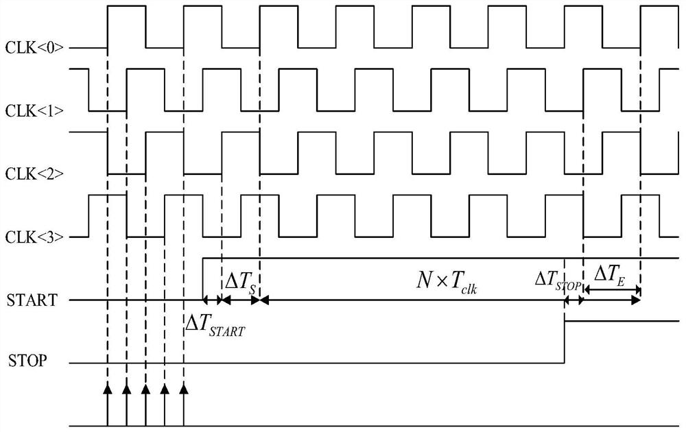
[0049] refer to Figure 5a , Figure 5b as well as Image 6 , in working mode 4, the working mode control module transmits the START signal to the time quantization module 1, and transmits three consecutive rising edges of the STOP signal to the time quantization modules 2, 3, and 4 in sequence. In this working mode, the time quantization m...

Embodiment 3

[0051] As an optional embodiment of the present invention, such as Figure 7 As shown, the working mode control module includes: 2-4 decoders and four control units, each control unit includes: an inverter, a tri-state gate, a drive terminal and a logic control unit, each control unit The output terminal of the inverter in the control unit is connected to the input terminal of the tri-state gate in the control unit, and the output terminal of the tri-state gate in the control unit is respectively connected to the input terminal of the drive terminal in the control unit and the output terminal of the logic control unit. The two control units are independent of each other. After the 2-4 decoder inputs the working mode control code, it outputs four ways of working mode control signals. The working mode control signal of each way is input to the logic control unit in the corresponding control unit. The i-th control unit The internal inverter inputs the time signal of the i-th chan...


PUM


Abstract

The embodiment of the invention provides a time-to-digital converter with multiple working modes, a working mode selection module is used for processing the input time signal, so that the input time signal is distributed to a time quantification module, and multiple types of detection functions are completed in combination with a multi-channel structure; meanwhile, the time quantification module selects the reference clock from the multi-phase clocks at the respective channels based on the gating signal, thereby avoiding the time sequence constraint which is difficult to satisfy and is introduced by directly inputting the reference clock signal into each channel in a conventional scheme, achieving the localization of the time sequence, enabling the first two stages of quantification time sequences of each time quantification module to be synchronous, therefore, system errors which cannot be eliminated in a traditional time-to-digital converter scheme are converted into fixed deviationswhich can be eliminated at the same time, and the measurement precision and the measurement reliability are greatly improved.

Description

technical field [0001] The invention belongs to the technical field of laser radar optical signal receiver systems, and relates to a time-to-digital converter with multiple working modes. Background technique [0002] Lidar ranging is a commonly used ranging technology. Its working principle is: when the laser emitter emits laser light on the target object to be detected, the laser echo reflected by the target object works in a linear mode. The avalanche photodiode receives and converts it into a current signal, and then the pulse current generated by the avalanche photodiode is linearly converted into a voltage signal by the front-end analog receiver, and then the time-to-digital converter is used to obtain the time-of-flight information of the pulse, so the time-digital The measurement accuracy, detection efficiency, and response time of the converter (TDC) put forward extremely high requirements. [0003] like figure 1 As shown, in the traditional solution, the TDC is c...

Claims


Application Information

Patent Timeline
Patent Type & Authority Applications(China)
IPC IPC(8): G01S7/4865
CPCG01S7/4865
Inventor 马瑞云越恒张玮朱樟明刘马良
Owner 西安芯辉光电科技有限公司
Why Eureka
Try Eureka