Method for connecting a catheter balloon with a catheter shaft of a balloon catheter

a technology of which is applied in the field of connecting a catheter shaft and a catheter balloon with a catheter shaft of a balloon catheter, can solve the problems of high total technical effort, complicated adjustment, and manual correction of the apparatus, and achieve the effect of reducing the technical effor

Inactive Publication Date: 2010-08-31
ABBOTT INT ENTERPRISES LTD
View PDF202 Cites 5 Cited by
  • Summary
  • Abstract
  • Description
  • Claims
  • Application Information

AI Technical Summary

Benefits of technology

[0006]It is thus the object of the present invention to provide a method for connecting a catheter balloon with a catheter shaft of a balloon catheter the technical effort of which is lower and the welding results of which are improved compared to prior art.
[0008]One advantage of the method according to the invention is that any desired materials can be used for the catheter balloon and the catheter shaft or catheter tube, respectively, since an adaptation to the radiation source to be used can be carried out by the welding energy absorbing device. During assembly the welding energy absorbing device defines the exact position at which welding is carried out afterwards or energy is injected, respectively. Consequently, no complex machine adjustment has to be carried out, since the required localization of the light beam is achieved by this external welding energy absorbing device which can be arranged exactly in the area of the desired weld in the area of the fixation site. A higher degree of automation of the welding apparatus is thus possible, involving at the same time higher accuracy and thus higher quality of the weld.
[0009]In addition to this, a distinction can be made between energy injection and fixation or sealing, respectively, of the welding site in the given arrangement, which makes an intensive flow of material possible. A displacement of material during the welding process and / or an intensive mixture of material are thus possible.
[0010]Furthermore, another advantage is that the method according to the invention is independent of the energy source, so that a variety of different radiation sources can be used.
[0011]As a particularly simple pre-fixation a heat shrink tubing can be used, which is applied to the pre-fixation site and is capable of fixing and sealing the fastening portion to be welded with the catheter shaft.

Problems solved by technology

However, this adjustment is very complicated, prone to errors and often requires manual correction of the apparatus.
In addition to that, laser welding involves the problem that the total technical effort is very high and that examinations carried out in the context of the invention have shown that poor uniformity of the weld is often the result.

Method used


Image

  • Method for connecting a catheter balloon with a catheter shaft of a balloon catheter
  • Method for connecting a catheter balloon with a catheter shaft of a balloon catheter

Examples


Embodiment Construction

[0019]Selected embodiments of the present invention will now be explained with reference to the drawings. It will be apparent to those skilled in the art from this disclosure that the following descriptions of the embodiments of the present invention are provided for illustration only and not for the purpose of limiting the invention as defined by the appended claims and their equivalents.

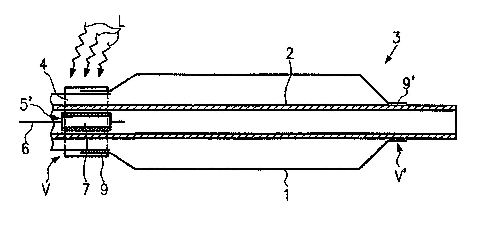
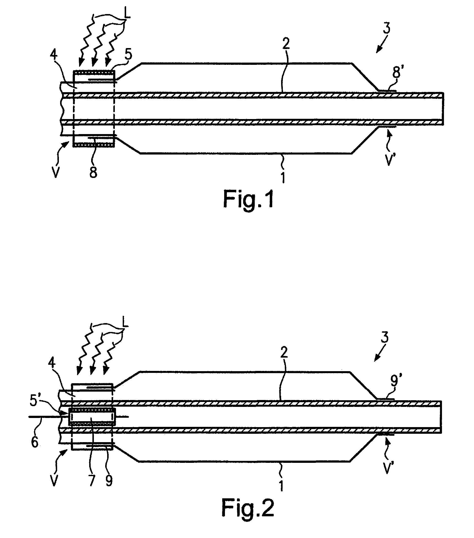
[0020]Referring to FIGS. 1 and 2, a proximal area of a balloon catheter 3 is illustrated in accordance with a first embodiment of the present invention. In this area a catheter balloon 1 is to be fastened on a catheter shaft 2 at two fixation sites V or V′, respectively, via fastening portions 8 or 8′, respectively. In order to explain the inventive method reference is made below to the schematically considerably simplified representation of the area of the fixation site V, the principles of which may also be used at the site V′.

[0021]In FIG. 1, an embodiment of the inventive method is shown, in wh...


PUM

PropertyMeasurementUnit
areaaaaaaaaaaa
radiation energyaaaaaaaaaa
energyaaaaaaaaaa

Abstract

A method for connecting a catheter balloon with a catheter shaft of a balloon catheter that improves the welding quality of a weld between the catheter balloon and the catheter shaft of the balloon catheter. Preferably, a welding energy absorbing device is arranged, preferably in the form of a colored tubing, in the area of a fixation site after attaching a pre-fixation and then to irradiate this welding energy absorbing device with the radiation energy to carry out the welding. After the welding the pre-fixation and the welding energy absorbing device are removed.

Description

BACKGROUND OF THE INVENTION[0001]1. Field of the Invention[0002]This invention generally relates to a method for connecting a catheter balloon with a catheter shaft of a balloon catheter.[0003]2. Background Information[0004]In a known method this connection is carried out by local welding, for example by means of laser welding. This local welding requires locating the light beam on the connection site. In order to do so, for carrying out the known method the machine has to be adjusted exactly or the welding site has to be positioned exactly, respectively. However, this adjustment is very complicated, prone to errors and often requires manual correction of the apparatus. In addition to that, laser welding involves the problem that the total technical effort is very high and that examinations carried out in the context of the invention have shown that poor uniformity of the weld is often the result. In addition to that, in this method the material must be adapted to the radiation sour...

Claims


Application Information

Patent Timeline
Patent Type & Authority Patents(United States)
IPC IPC(8): B32B37/00
CPCB29C65/18B29C66/63B29C65/7855B29C66/1122B29C66/612B29C66/53241B29C65/14B29C65/1441B29C65/1445B29C65/16B29C65/68B29C66/5344B29C65/245B29C2791/009B29L2031/7543B29C65/1635
Inventor QUINT, BODONIELSEN, STEVAN
Owner ABBOTT INT ENTERPRISES LTD
Why Eureka
Try Eureka