
Automobile, driving system and control method thereof

The technology of a driving system and a control method, which is applied in the field of vehicles, can solve the problems of insufficient power, large radial space occupied by the driving system, and influence on the layout of the whole vehicle, so as to avoid insufficient power, facilitate the layout of the whole vehicle, and reduce the radial space occupation effect of demand

Active Publication Date: 2019-11-29
SAIC MOTOR
View PDF17 Cites 2 Cited by
  • Summary
  • Abstract
  • Description
  • Claims
  • Application Information

AI Technical Summary

Problems solved by technology

[0002] In the existing electric vehicles, the drive system mainly uses parallel shaft mechanism to achieve deceleration and torque increase. With this structure, in order to achieve a large speed ratio, three parallel shafts are usually required, which makes the radial occupation of the entire drive system The space is large, seriously affecting the layout of the vehicle
Moreover, the existing drive system generally adopts a single-motor drive scheme, which is prone to insufficient power during high-speed driving or climbing.

Method used


Image

  • Automobile, driving system and control method thereof
  • Automobile, driving system and control method thereof
  • Automobile, driving system and control method thereof

Examples


Embodiment 1

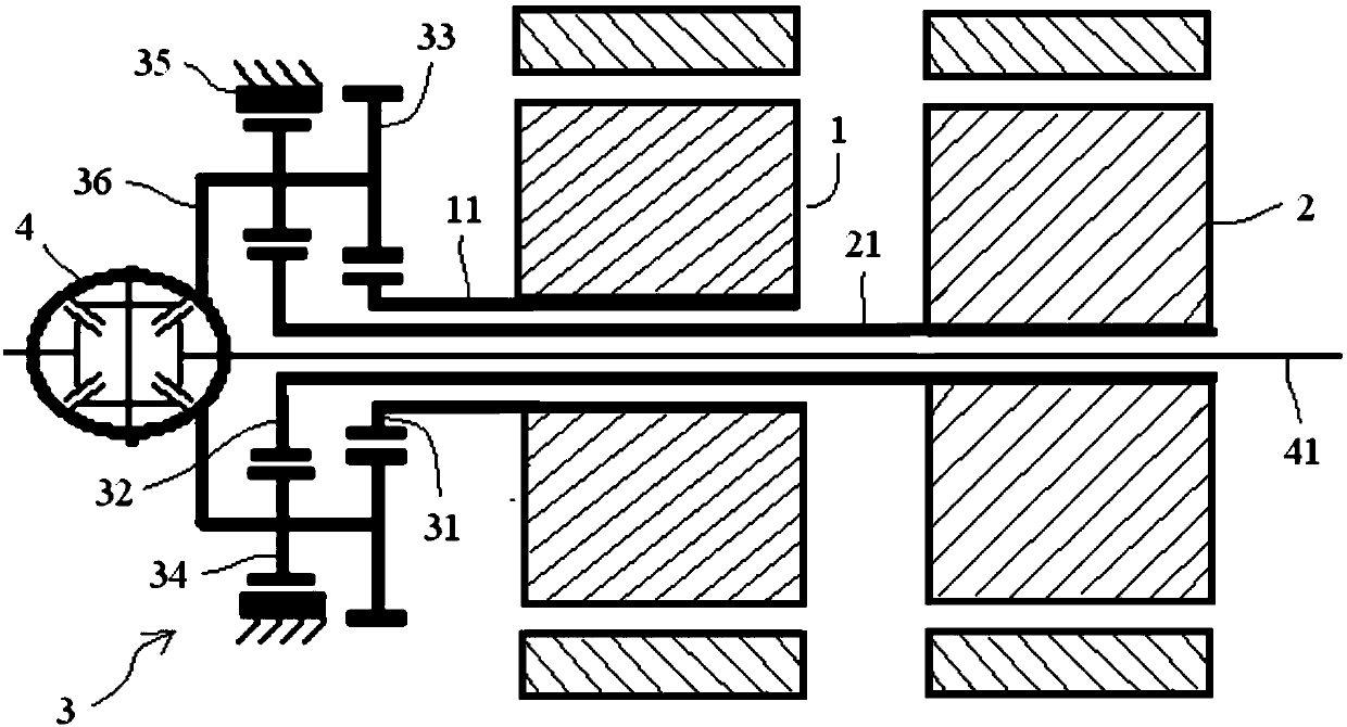
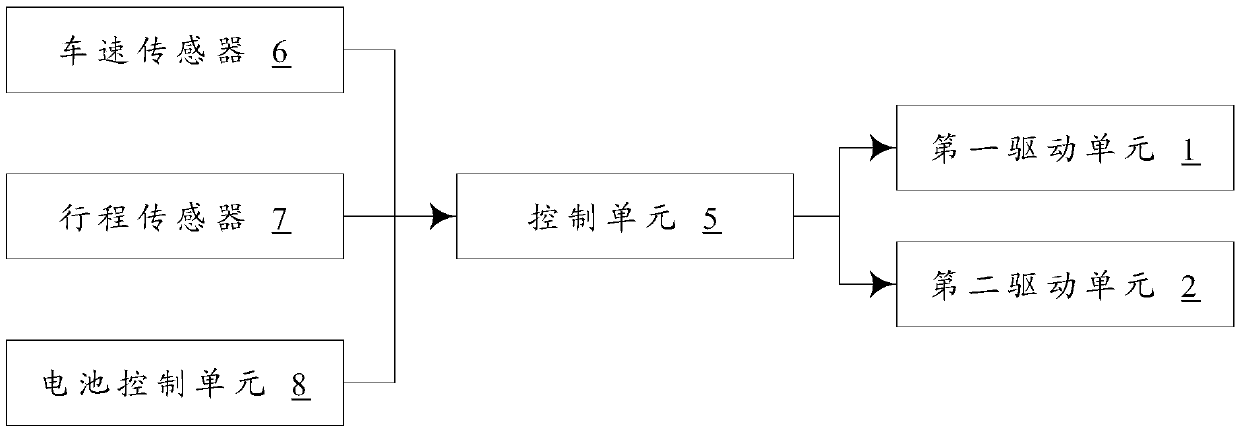
[0036] Please refer to Figure 1-2 , figure 1 It is a schematic structural diagram of a specific embodiment of the drive system provided by the present invention, figure 2 This is the control principle diagram of the drive system provided by the present invention.

[0037] like figure 1 As shown, the present invention provides a drive system applied to an automobile, comprising a first drive unit 1 , a second drive unit 2 and a deceleration unit 3 . Different from the prior art, the deceleration unit 3 is a planetary gear mechanism, and its structure is more compact, which can reduce the radial dimension of the deceleration unit 3, thereby reducing the radial space occupation requirement of the drive system, so as to improve the power density of the drive system, And it is convenient for the layout of the whole vehicle; moreover, the planetary gear mechanism has a lower slip rate and a larger bearing capacity, which can improve the power transmission efficiency of the redu...

Embodiment 2

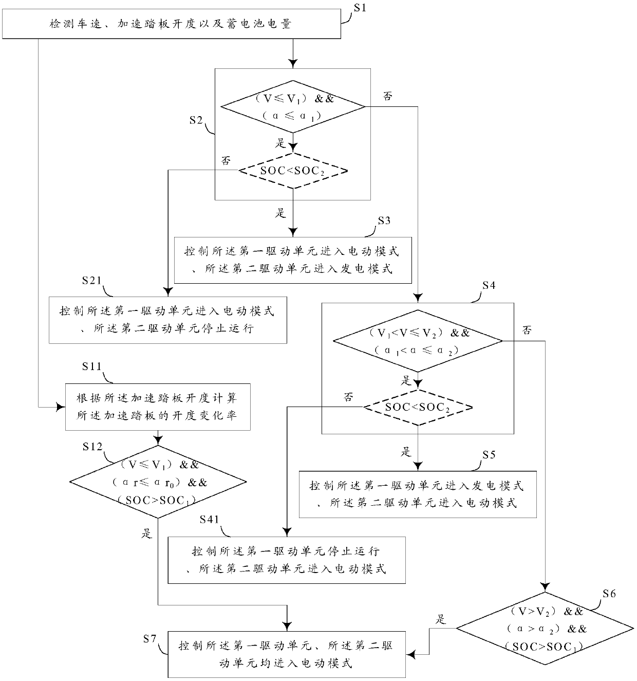
[0054] Please refer to image 3 , image 3 It is a schematic flowchart of the control method of the drive system provided by the present invention.

[0055] For the solution in Embodiment 1 that both drive units are motors, and both motors have an electric motor mode and a power generation mode, the present invention also provides a control method for a drive system, such as image 3 As shown, the control method includes the following steps:

[0056] In step S1, the vehicle speed V, the accelerator pedal opening α, and the battery power SOC are detected.

[0057] In practical applications, the vehicle speed sensor 6, the travel sensor 7 and the battery control unit 8 mentioned in Embodiment 1 can be used to measure the specific values ​​of the above parameters.

[0058] Step S2, determine whether the vehicle speed V is less than or equal to the first vehicle speed V 1 , whether the accelerator pedal opening α is less than or equal to the first amplitude α 1 , if yes, go t...

Embodiment 3

[0082] The present invention also provides an automobile, including a drive system, the drive system is the drive system involved in Embodiment 1, and the drive system can adopt the control method involved in Embodiment 2.

[0083] Since the drive system in embodiment 1 and the control method in embodiment 2 have already possessed the above-mentioned technical effect, then, the automobile with the drive system and the control method using the drive system should also possess similar technical effects, so in I won't go into details here.


PUM


Abstract

The invention discloses an automobile, a driving system and a control method thereof. The driving system is applied to the automobile and includes a first driving unit, a second driving unit, and a deceleration unit, wherein the deceleration unit includes coaxial first and second sun gears; the first sun gear is meshed with a first planetary gear; the second sun gear is meshed with a second planetary gear; the center distance between the first sun gear and the first planetary gear is equal to the center distance between the second sun gear and the second planetary gear; the first planetary gear and the second planetary gear are connected to the same planet carrier; the second planetary gear is also meshed with a fixed internal gear ring; the first driving shaft of the first driving unit isconnected to the first sun gear; the second driving shaft of the second driving unit is connected to the second sun gear; and the planet carrier is used for output. The driving system provided by thepresent invention is compact in structure, can be conveniently arranged on the entire vehicle, and has two driving units which can provide great power.

Description

technical field [0001] The present invention relates to the technical field of vehicles, and in particular, to an automobile, a driving system and a control method thereof. Background technique [0002] In the existing electric vehicle, the drive system mainly uses a parallel shaft mechanism to achieve deceleration and torque increase. With this structure, in order to achieve a larger speed ratio, three parallel shafts are usually required, which makes the radial occupation of the entire drive system. The space is large, which seriously affects the layout of the vehicle. Moreover, the existing drive system generally adopts a single-motor drive scheme, which is prone to lack of power during high-speed driving or climbing. [0003] Therefore, how to provide a driving system with a compact structure and sufficient power is still a technical problem to be solved urgently by those skilled in the art. SUMMARY OF THE INVENTION [0004] The purpose of the present invention is to...

Claims


Application Information

Patent Timeline
Patent Type & Authority Applications(China)
IPC IPC(8): B60L15/20B60K17/04
CPCB60L15/20B60K17/04B60L2240/461B60L2220/42Y02T10/72
Inventor 柴少彪黄维宗子淳孙晓文黄岩松李军
Owner SAIC MOTOR
Learn More