Connecting structure of steel pipe column and steel beam

A technology for connecting structures and steel pipe columns, which is applied in the direction of building construction and construction, can solve the problems of increasing the relative wall thickness of steel pipe columns, achieve the effects of increasing anchorage length, avoiding welding operations, and facilitating construction

Inactive Publication Date: 2019-11-29
SHANDONG UNIV +1
View PDF8 Cites 3 Cited by
  • Summary
  • Abstract
  • Description
  • Claims
  • Application Information

AI Technical Summary

Problems solved by technology

[0006] The purpose of this application is to provide a connection structure between a steel pipe column and a steel beam in view of the defects in the prior art. By setting the connecting member as an intermediate piece between the steel pipe column and the steel beam, and matching the preset threaded holes on the steel pipe column, the problem is solved. It solves the problem that the closed-section column joints in the steel structure are difficult to be connected by bolts. The relative wall thickness of the steel pipe column is increased by the connecting member, so as to meet the needs of bolt anchorage. It is fixed by screw fit connection, which avoids the welding process on the construction site and realizes Fully assembled construction

Method used


Image

  • Connecting structure of steel pipe column and steel beam
  • Connecting structure of steel pipe column and steel beam
  • Connecting structure of steel pipe column and steel beam

Examples


Embodiment 1

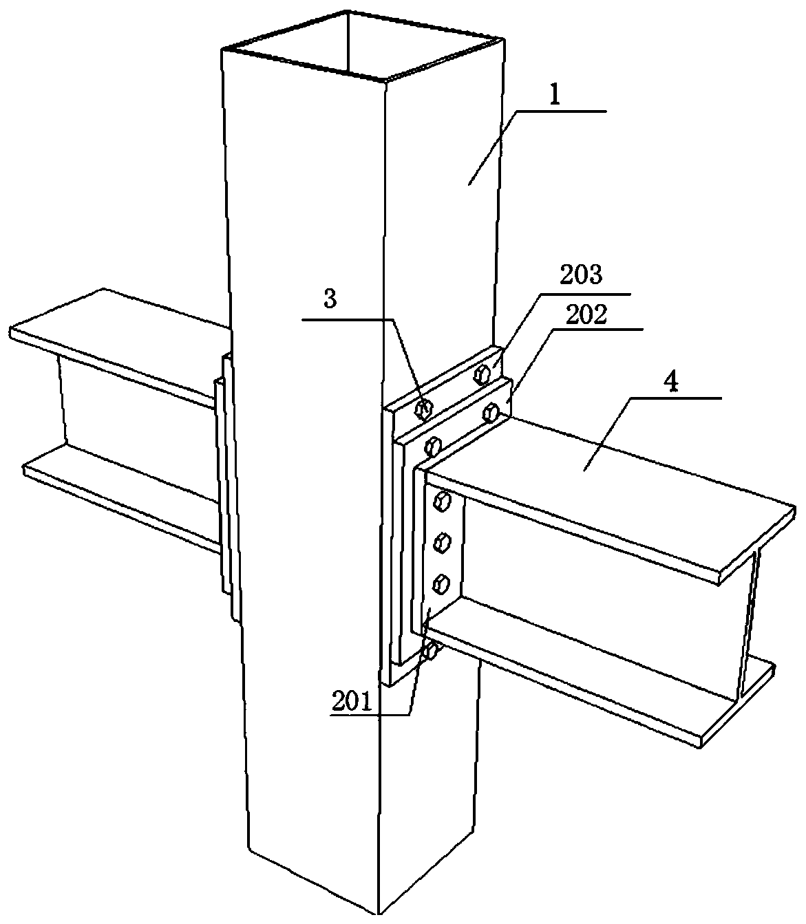
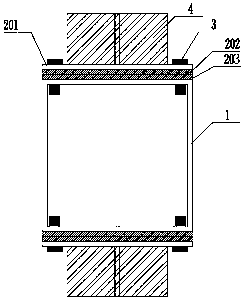
[0040] In a typical implementation of the present application, such as Figure 1-Figure 2 As shown, an auxiliary connection structure for connecting steel beams and steel pipe bodies is proposed.

[0041] A connection structure for a steel pipe column and a steel beam, including a connection member, the connection member includes at least one connection plate 202 (203 may not be included, described as existing 203 in this example), and one side of the connection member is used for laminating the steel pipe The other side of the column 1 is used to connect the end plate 201 of the steel beam 4. The end plate 201 is provided with a through hole, and the connecting plates 202 and 203 are provided with a first threaded hole, and the first threaded hole is equipped with A unilateral bolt 3, which passes through the end plate 201, connecting members 202 and 203, and the wall of the steel pipe column 1 in sequence, and the threaded part of the unilateral bolt 3 is connected with the ...

Embodiment 2

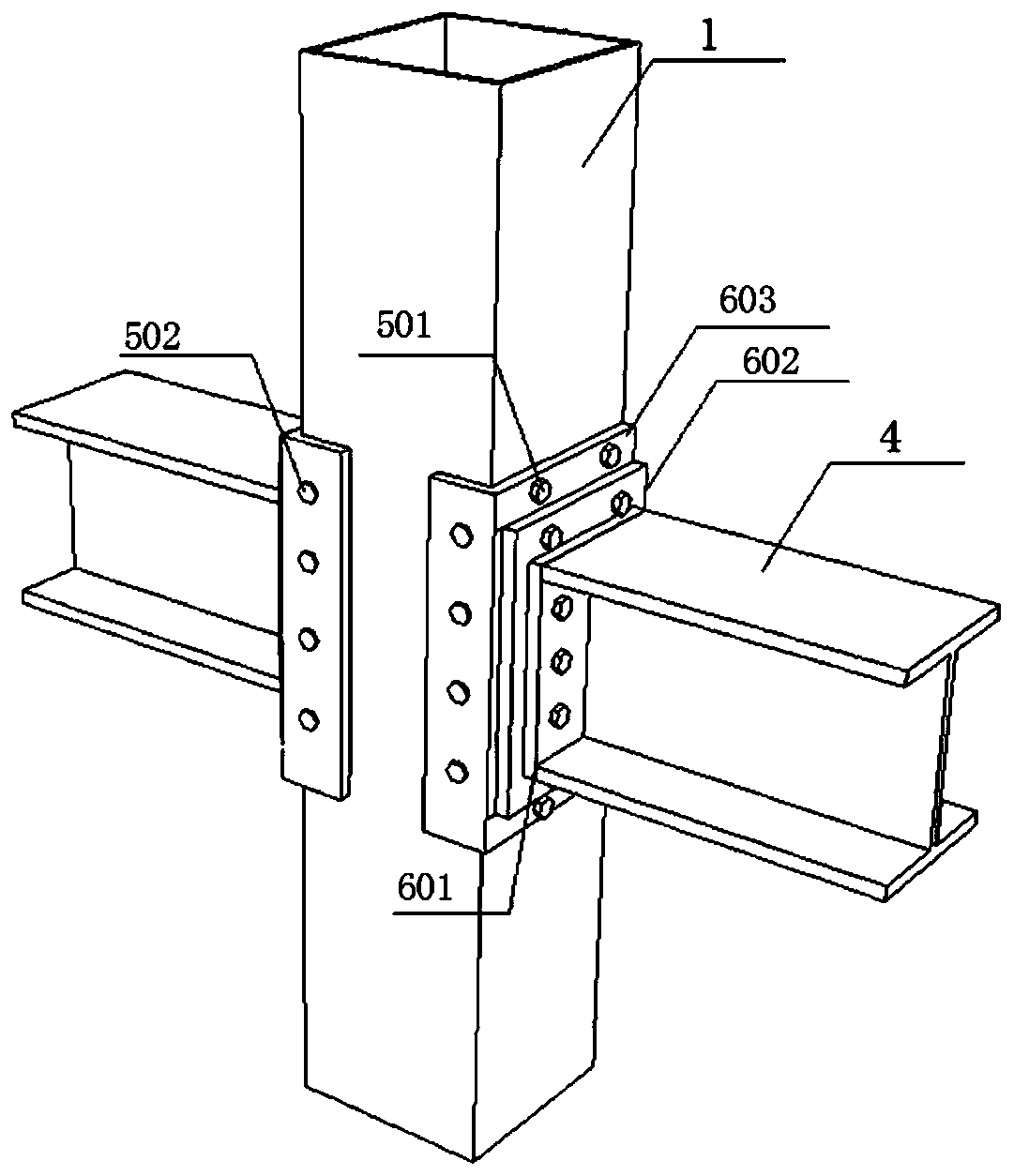
[0048] The present application also provides another connection structure between steel pipe columns and steel beams, such as Figure 3-4 As shown, it is different from the connecting member in Embodiment 1.

[0049] It includes a connecting member, the connecting member includes a first connecting plate, and the first connecting plate includes a bent plate and a superimposed plate, one side of the superimposed plate is attached to the first side of the steel pipe column, and the other side is connected to the end plate of the steel beam , the bent plate is attached to the second side adjacent to the first side of the steel pipe column, the first connecting plate is provided with a first threaded hole, and the first threaded hole is matched with a first unilateral bolt and The second unilateral bolt is provided with a through hole on the end plate of the steel beam, and the first unilateral bolt passes through the through hole and the first threaded hole on the superimposed pl...

Embodiment 3

[0058] The present application also provides a third connection structure between a steel pipe column and a steel beam, the difference from Embodiment 2 lies in the first connection plate;

[0059] In this embodiment, the connecting member includes two first connecting plates 802. The first connecting plate includes a bent plate and a superimposed plate. The end plate of the beam, the bent plate is used to fit the second side adjacent to the first side of the steel pipe column, a gap is provided between the two first connecting plates, and the gap is used as an axis-symmetric arrangement;

[0060] The first connecting plate is a bent structure, including a bent plate and a superimposed plate connected to each other, the bent plate is perpendicular to the superimposed plate, and the two bent plates corresponding to the two first connecting plates are used for A pair of second sides of the steel pipe column are attached respectively; the steel beam end plate 801 is between the f...


PUM


Abstract

The invention discloses a connecting structure of a steel pipe column and a steel beam. A connecting component comprises at least one connecting plate, one side of the connecting plate is used for being attached to the steel pipe column, the other side is used for being connected with an end plate of the steel beam, the end plate is provided with a through hole, the connecting plate is provided with a first threaded hole, the first threaded hole is matched with a unilateral bolt, the unilateral bolt sequentially penetrates through the end plate, the connecting component and the steel pipe column wall, the threaded part of the unilateral bolt is sequentially matched with the first threaded hole and a second threaded hole pre-formed in the steel pipe column, and the connecting component is matched with the unilateral bolt to enable the steel beam to be connected with the steel pipe column and to be fixed. The connecting component plays a role of connection and is also an enhancing component at the same time, through the connecting component, the anchoring length of the bolt, the thickness of the steel pipe column wall and the effective thickness of the outer side of the beam end plate are increased, the anti-deformability of the end plate outside the beam and the steel pipe column is improved, and the anchoring length of the bolt is increased.

Description

technical field [0001] This application relates to the field of steel structure joints, specifically the connection structure of steel pipe columns and steel beams. Background technique [0002] At present, there are three main ways to connect steel structures: bolted connection, welded connection, and bolt-welded hybrid connection. Among them, the welded connection has the largest strength and rigidity, but its construction is greatly affected by the weather and site environment, and the technical requirements for welding workers are relatively high, and the construction speed is slow, and the construction quality is not easy to guarantee; while the bolted connection is fast and simple to install, mechanically The advantages of stable performance, high degree of assembly, and convenient inspection and replacement have become a more ideal connection form. [0003] The inventors found that the pipe column has better load-bearing performance than the steel pipe column with op...

Claims


Application Information

Patent Timeline
Patent Type & Authority Applications(China)
IPC IPC(8): E04B1/24E04B1/58
CPCE04B1/2403E04B2001/2415E04B2001/2418
Inventor 刘梅尤洋王培军周生展孙强孙健于建欣陈俊霞胡显峰赵辉尚衍卫
Owner SHANDONG UNIV
Why Eureka
Try Eureka