Working condition conversion method of speed regulator of pumped storage unit

A technology of pumped storage unit and conversion method, applied in the field of electric power system, can solve the problems of cross-connection, difficult to guarantee reliability, and difficult to guarantee the reliability of process conversion, so as to prevent wrong working condition conversion, improve overall reliability, complex The effect of the transformation relationship is clear and clear

Inactive Publication Date: 2019-11-29
NANJING NARI WATER RESOURCES & HYDROPOWER TECH CO LTD +4
View PDF4 Cites 7 Cited by
  • Summary
  • Abstract
  • Description
  • Claims
  • Application Information

AI Technical Summary

Problems solved by technology

When the number of processes is small and independent of each other, the ladder diagram is easier to solve, but the pumped storage unit has dozens of working conditions and there is a conversion relationship between them, it is difficult to handle with the ladder diagram method, and the readability is very poor , even if it is designed, it is difficult to ensure that the process conversion is reliable
Although the graphical design method is concise, intuitive, vivid, and highly readable, generally advanced PLCs support graphical programming, but its essence is an improvement of the ladder diagram. When there are many program modules and are closely related to each other, the graphical method is also Difficult to describe clearly, there are problems such as connection crossover, conversion confusion, reliability is difficult to guarantee, etc.
[0003] Therefore, when the number of working conditions is small and relatively simple, the ladder diagram programming method is generally used to design, but for more than 20 complex working conditions and interrelationships of the pumped storage unit, the ordinary ladder diagram design method is difficult to solve and cannot guarantee safety and reliability.

Method used


Image

  • Working condition conversion method of speed regulator of pumped storage unit
  • Working condition conversion method of speed regulator of pumped storage unit
  • Working condition conversion method of speed regulator of pumped storage unit

Examples


Embodiment Construction

[0054] The present invention will be further described below in conjunction with the accompanying drawings. The following examples are only used to illustrate the technical solution of the present invention more clearly, but not to limit the protection scope of the present invention.

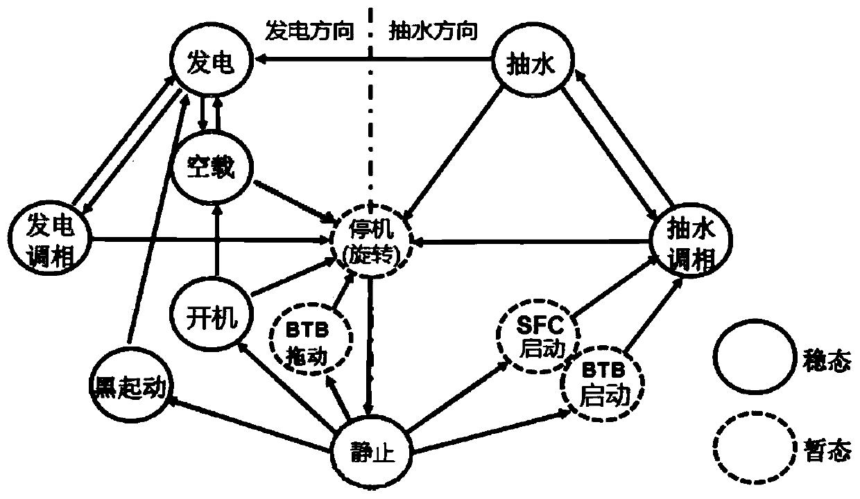
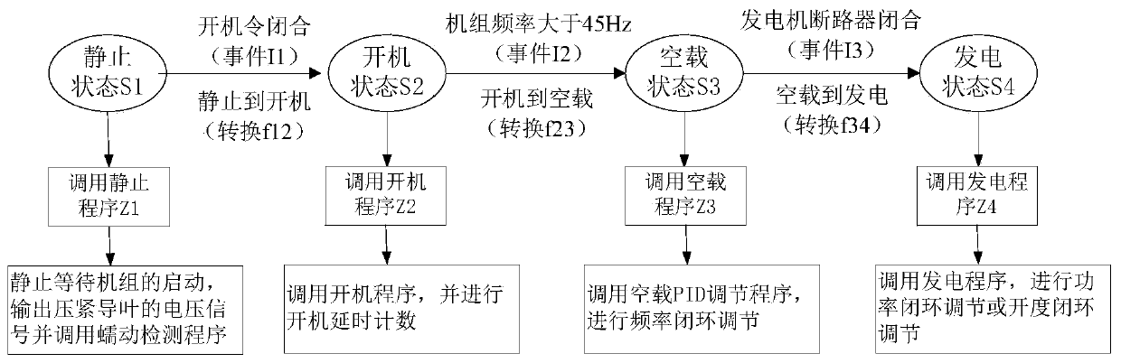
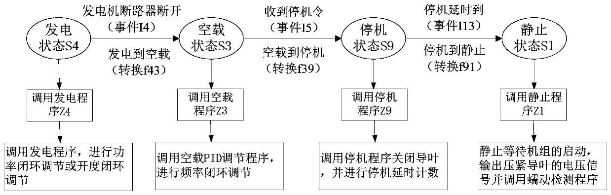
[0055] In the control of the pumped storage unit, the unit is always in a certain working state and completes a certain task under a certain working condition, and the conversion between working conditions is driven by external events, so This working condition transition process can be described by a finite state machine. According to the concept of finite state machine mentioned above, analyzing the conversion relationship between the working conditions of the pumped storage unit, the specific definition of the quintuple of the finite state machine used to describe the conversion of the working conditions of the pumped storage unit can be obtained as follows:

[0056]S is the set of all worki...


PUM


Abstract

The invention discloses a working condition conversion method of a speed regulator of a pumped storage unit. The method comprises the following steps: (1) a state set, an event set, a state conversionfunction and an action set of a finite state machine are obtained by combing through various working conditions, external input events, conversion conditions among the various working conditions andaction programs executed by the various working conditions of the pumped storage unit on the basis of a finite state machine principle, wherein the state set, the event set, the state conversion function and the action set of the finite state machine are used for describing working condition conversion of the pumped storage unit; and (2) based on the state set, the event set, the conversion function and the action set of the finite state machine, the multiple working conditions, complex conversion relations and execution programs of the pumped storage unit are programmed. The method has the advantages that the limitation of a conventional trapezoid graph and a graph design method is overcome, the occurrence of wrong working condition conversion is effectively prevented, and the overall reliability of equipment is improved.

Description

technical field [0001] The invention relates to a method for switching working conditions of a governor of a pumped storage unit, and belongs to the technical field of electric power systems. Background technique [0002] In recent years, with the rapid development of my country's power grid construction and new energy, the security and stability of the power grid and the consumption of new energy have become increasingly prominent. Pumped storage power stations have been widely used as the most effective energy storage method for peak shaving and valley filling. Compared with conventional power stations, pumped storage units have more working conditions, complex conversion methods, frequent conversions, and higher safety and reliability. When the number of processes is small and independent of each other, the ladder diagram is easier to solve, but the pumped storage unit has dozens of working conditions and there is a conversion relationship between them, it is difficult to...

Claims


Application Information

Patent Timeline
IPC IPC(8): F03B15/00F03B13/06F03B15/06F03B15/08F03B15/18
CPCF03B13/06F03B15/00F03B15/06F03B15/08F03B15/18Y02E10/20Y02E60/16
Inventor 蔡卫江任格施海东章姝俊钱凤梁廷婷魏文力牛翔宇衣传宝荣红
Owner NANJING NARI WATER RESOURCES & HYDROPOWER TECH CO LTD
Why Eureka
Try Eureka