Hypersonic aircraft trajectory tracking control method for performance recovery

A hypersonic, control method technology, applied in vehicle position/route/altitude control, non-electric variable control, control/regulation system, etc., can solve the problem of engine stall, scramjet propulsion performance degradation, scramjet work Narrow corridors, etc.

Inactive Publication Date: 2019-11-29
HARBIN INST OF TECH
View PDF4 Cites 10 Cited by
  • Summary
  • Abstract
  • Description
  • Claims
  • Application Information

AI Technical Summary

Problems solved by technology

[0003] In order to solve the problem that the working corridor of the scramjet engine is relatively narrow, the present invention requires relatively strict air intake conditions to support stable propulsion performance, but too low speed and too large angle of attack will reduce the propulsion performance of the scramjet engine, even Cause the engine to stall, if the scramjet engine is stalled due to the stall of the aircraft, the hypersonic vehicle will not be able to recover its performance autonomously. A trajectory tracking control method for the air-breathing hypersonic vehicle considering the constraints of the engine's working conditions and performance recovery is proposed. In this method, the logarithmic barrier function is used to replace the general quadratic function to design the Lyapunov function, and the trajectory tracking control method of the hypersonic vehicle with speed constraints is realized; in view of the situation that the engine stalls unexpectedly due to the stall, the trajectory adjustment method is used to make The hypersonic vehicle can autonomously restore the restart conditions of the engine, and then realize the stable tracking of the original desired trajectory again

Method used


Image

  • Hypersonic aircraft trajectory tracking control method for performance recovery
  • Hypersonic aircraft trajectory tracking control method for performance recovery
  • Hypersonic aircraft trajectory tracking control method for performance recovery

Examples


Embodiment 1

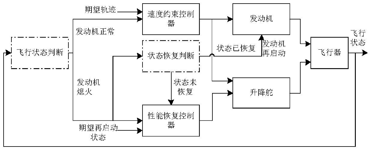
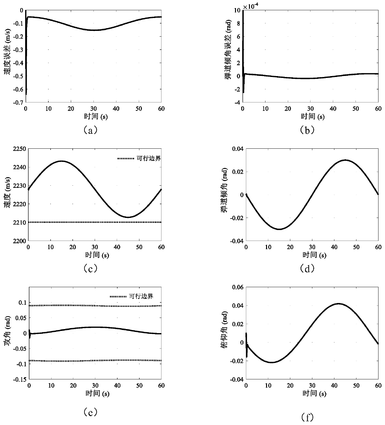
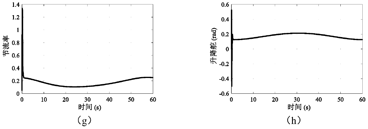
[0077] In this embodiment, in order to solve the problem that the working corridor of the scramjet engine is relatively narrow, relatively strict air intake conditions are required to support stable propulsion performance, and too low speed and too large angle of attack will reduce the propulsion performance of the scramjet engine. Even cause the engine to stall. If the scramjet engine is stalled due to aircraft stall, the hypersonic vehicle will not be able to recover its performance autonomously. A trajectory tracking control method for hypersonic vehicle oriented to performance recovery is proposed. Based on the working conditions of the supersonic vehicle engine, the lower limit of its flight speed within the reasonable range of angle of attack is obtained; then, with the lower limit of the speed as a constraint, the logarithmic barrier function is used instead of the general quadratic function to design the Lyapunov function, and the realization of the function with Veloci...


PUM


Abstract

The invention provides a hypersonic aircraft trajectory tracking control method for performance recovery and belongs to the technical field of air-breathing hypersonic aircraft trajectory tracking control. The method comprises the steps that 1, the specific engine safety constraint boundary is obtained; 2, the speed tracking error upper limit of the hypersonic flight vehicle is set according to the minimum speed constraint and the speed expected trajectory; 3, for the longitudinal speed dynamic state of the hypersonic aircraft, a dynamic inverse control method is adopted to obtain a throttlingrate control law of a speed subsystem; 4, a system dynamic model is converted into an error dynamic model to obtain the backstepping control law by adopting the backstepping method aiming at the height dynamic state of the hypersonic aircraft; 5, the control strategy is established to realize restarting of an engine; 6, the starting condition of the engine is obtained through calculation; and 7,after the aircraft reaches the starting condition, the engine is ignited again, performance recovery of a propulsion system is completed, the aircraft is switched back to a nominal controller, and then the original expected trajectory is tracked again.

Description

technical field [0001] The invention relates to a performance recovery-oriented hypersonic vehicle trajectory tracking control method, belonging to the technical field of air-breathing hypersonic vehicle trajectory tracking control. Background technique [0002] In order to achieve a higher lift-to-drag ratio and thus have a larger flight envelope, the air-breathing hypersonic vehicle generally adopts a waverider configuration, with a scramjet integrated in the belly of the fuselage, presenting a fuselage / propulsion Integrated configuration. This configuration also brings about the coupling of the propulsion system and the attitude of the fuselage, which brings certain difficulties to the design of the control system. Since the working corridor of the scramjet engine is relatively narrow, strict air intake conditions are required to support stable propulsion performance. The air intake conditions of the scramjet are mainly affected by the speed and attitude of the hyperson...

Claims


Application Information

Patent Timeline
Patent Type & Authority Applications(China)
IPC IPC(8): G05D1/10
CPCG05D1/101
Inventor 晁涛王松艳杨明王雨潇张登辉
Owner HARBIN INST OF TECH
Why Eureka
Try Eureka