
a calculation co 2 Numerical simulation method of flooding minimum miscibility pressure

A miscible pressure and numerical simulation technology, applied in design optimization/simulation, earthwork drilling and production, wellbore/well components, etc., can solve problems such as long measurement time, large influence of simulation results, high technical requirements, and achieve time-saving effects

Active Publication Date: 2021-09-28
PETROCHINA CO LTD
View PDF4 Cites 1 Cited by
  • Summary
  • Abstract
  • Description
  • Claims
  • Application Information

AI Technical Summary

Problems solved by technology

Among the experimental methods, the capillary experimental method is the most widely used, and is currently the internationally recognized standard method for measuring the minimum miscible pressure. The disadvantage is that the measurement time is too long
[0003] Among the theoretical calculation methods, the numerical simulation method is an important method for studying the effect of miscible displacement and designing miscible flooding. Generally speaking, the component model of miscible flooding is commonly used for simulation research, and the thin tube experiment is simulated by numerical simulation. The accuracy is reliable, but the problems that restrict the wide application of this method are: the thin tube model itself needs to consider the physical parameters of the target reservoir; the calculation accuracy is mainly based on the good fitting of PVT properties, and the PVT fitting technology requires high requirements; Simulation results have a big impact

Method used


Image

  • a calculation co  <sub>2</sub> Numerical simulation method of flooding minimum miscibility pressure
  • a calculation co  <sub>2</sub> Numerical simulation method of flooding minimum miscibility pressure
  • a calculation co  <sub>2</sub> Numerical simulation method of flooding minimum miscibility pressure

Examples


Embodiment 1

[0055] 1) Establish a long thin tube model

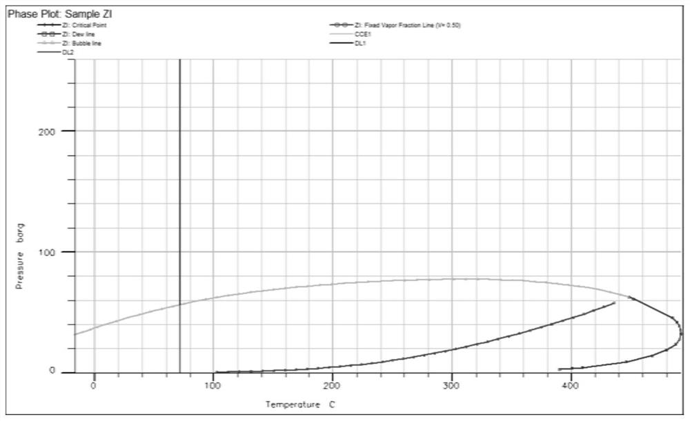
[0056] The one-dimensional thin tube model established this time is a miscible component model containing oil and water two phases, see figure 1 , figure 1 It is the long thin tube model diagram of the establishment of the present invention, the grid scale is 400 × 1 × 1, each grid is 5 cm long in the X direction, 0.4 cm long in the Y direction and Z direction, and the permeability in the X, Y, and Z directions Both are 5000mD, the porosity is 20%, the reservoir temperature is 71.6°C, the rock compressibility coefficient is 0.00002, the original oil saturation is 1, the original water saturation is 0, the original gas saturation is 0, and the oil-gas phase permeability curve for the experimental data.

[0057] In terms of well definition, an injection well (I1) is defined at the grid (1,1,1), the grid (1,1,1) is opened, the conductivity coefficient is 3000, the injection medium is defined as gas, and the injection rate is 1cm 3 ...


PUM


Abstract

The invention discloses a method for calculating CO 2 Numerical simulation method for flooding minimum miscibility pressure involving CO 2 flooding enhanced oil recovery technical category. The numerical simulation method comprises the following steps: establishing a general model of long thin tube components; inputting the crude oil component parameters, flash separation and differential separation experimental data of the target oil reservoir in the PVTi module of the numerical simulation software; Batch batch, using the three-parameter state equation for regression calculation of the experimental data of flash separation and differential separation of crude oil components in the batch results; the screened regression parameters are used as fitting parameters, and the weight of the fitting parameters is set to achieve fast Component fitting; the PVTi module derives the state equation parameters based on the fitting data to obtain the long thin tube composition numerical model; under different reservoir pressure conditions, run the long thin tube component numerical model, and output the corresponding full oilfield recovery factor ; using its simulation to calculate the CO of the target reservoir 2 drive minimum miscible pressure.

Description

technical field [0001] The invention belongs to the field of oil and gas field development and relates to CO 2 flooding enhanced oil recovery technology category, especially a calculation of CO 2 Numerical simulation method of flooding minimum miscibility pressure. Background technique [0002] CO 2 The minimum miscible pressure with crude oil is to judge CO 2 Whether the flooding achieves miscibility and the key parameters to predict the effect, the current determination of CO 2 There are two types of minimum miscible pressure flooding methods, one is the experimental method, including the thin tube experiment method, interfacial tension method and bubble riser method; the other is the theoretical calculation method, including the empirical formula method, multiple contact method, equation of state method, tie line analysis method and numerical simulation method. Among the experimental methods, the capillary experimental method is the most widely used, and is currently...

Claims


Application Information

Patent Timeline
Patent Type & Authority Patents(China)
IPC IPC(8): G06F30/20E21B43/16
CPCE21B43/164
Inventor 上官阳南李兆国张永强熊维亮雷欣慧李姝蔓康兴妹曾山杨金龙余光明
Owner PETROCHINA CO LTD
Learn More