
crm buck-flyback pfc converter with constant frequency control

A converter and filter technology, applied in control/regulation systems, output power conversion devices, DC power input conversion to DC power output, etc., can solve the problem of large switching frequency conversion range, complex EMI design, low power factor, etc. problem, to achieve the effect of PF improvement, efficiency improvement and output voltage ripple reduction

Active Publication Date: 2021-11-09
NANJING UNIV OF SCI & TECH
View PDF8 Cites 0 Cited by
  • Summary
  • Abstract
  • Description
  • Claims
  • Application Information

AI Technical Summary

Problems solved by technology

The advantages are simple control, high power factor in the high-voltage range, and no reverse recovery problem of the diode; the disadvantage is that the switching frequency of the switching tube within half a power cycle can be changed in a large range, the power factor in the low-voltage range is very low, the EMI design is complicated, and the efficiency is low.

Method used


Image

  • crm buck-flyback pfc converter with constant frequency control
  • crm buck-flyback pfc converter with constant frequency control
  • crm buck-flyback pfc converter with constant frequency control

Examples


Embodiment Construction

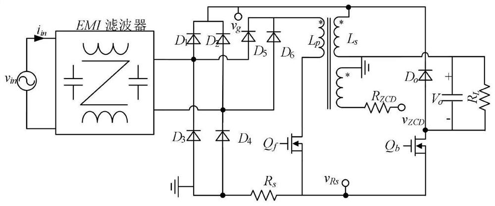
[0025] figure 1 It is the main circuit of Buck-FlybackPFC converter.

[0026] Make the following assumptions: (1) All devices are ideal; (2) The output voltage ripple is small compared to its DC value; (3) The switching frequency is much higher than the input voltage frequency.

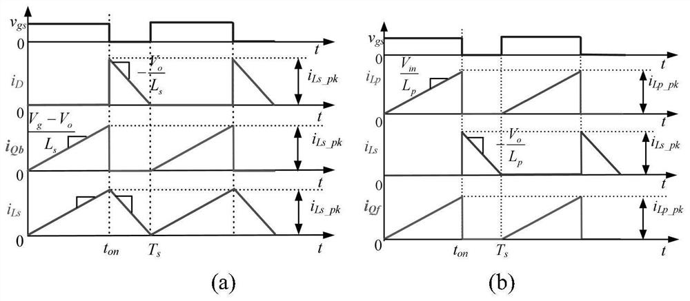
[0027] figure 2 The waveforms of the switching tube current and the inductor current in one switching cycle when the inductor current is critically continuous are given, where figure 2 (a) Waveform diagram when Buck topology works, figure 2 (b) Waveform diagram when working for the Flyback topology. When the input voltage v g less than the output voltage V o When the Flyback topology works, Q b off, Q f When turned on, D o cutoff, the inductance L p The voltage across it is v g , its current i Lp start with zero and start with v g / L p The slope rises linearly, the output filter capacitor C o supply power to the load; when Q f When turned off, according to the conservation of ampere ...


PUM


Abstract

The invention provides a CRM step-down-flyback PFC converter adopting constant frequency control, comprising a main power circuit, an input voltage digital feedforward circuit, an output voltage differential circuit, a feedback circuit, a state judgment circuit, a drive signal generation circuit, Comparing and multiplying circuits. The present invention introduces an input voltage digital feedforward circuit, an input voltage comparison circuit and a gating circuit to realize a double-fixed-frequency control mode, so that the switching frequencies of the switching tubes of the converter in the Buck stage and the Flyback stage are kept at different constant values ​​respectively.

Description

technical field [0001] The invention relates to an AC / DC converter technology, in particular to a constant frequency controlled CRM step-down-flyback PFC converter. Background technique [0002] Due to problems such as input current dead zone and switching tube floating ground, it is difficult for the traditional BuckPFC converter to meet the design technical requirements in many applications. In order to solve these problems, a buck-flyback PFC converter was proposed, which combines the Buck topology with the Flyback topology. When the input voltage is greater than the output voltage, the Buck topology works. When the input voltage is less than the output voltage, the Flyback Topology works. However, the traditional CRM buck-flyback PFC converter adopts constant on-time control. When the two topologies of the converter work, the on-time is equal, so that the switching frequency of the switching tube in the second half of the power frequency cycle of this control mode The ...

Claims


Application Information

Patent Timeline
Patent Type & Authority Patents(China)
IPC IPC(8): H02M7/219H02M1/42H02M3/335H02M1/15
CPCH02M1/15H02M1/42H02M3/33592H02M7/219H02M1/0058Y02B70/10
Inventor 马春伟姚凯张震邬程健管婵波李凌格陈杰楠
Owner NANJING UNIV OF SCI & TECH
Learn More