Fixing device of computer network automatic control system

An automatic control system, computer network technology, applied in the direction of casing/cabinet/drawer parts, cooling/ventilation/heating transformation, electrical components, etc. Problems such as the heat dissipation effect of the shell to achieve the effect of improving the heat dissipation effect

Pending Publication Date: 2019-11-29
麦瑞聪
View PDF0 Cites 0 Cited by
  • Summary
  • Abstract
  • Description
  • Claims
  • Application Information

AI Technical Summary

Problems solved by technology

[0003] The computer network automatic control system used in the actual production process is composed of multiple computer controllers. The multiple computer controllers are connected to the corresponding mechanical equipment to obtain the working signals of the mechanical equipment, and the multiple computer controllers are connected to each other. They are connected by signal wires to realize signal feedback processing, so corresponding controllers are fixed in the corresponding mechanical settings, but in the prior art, the bottom surface of the controller is directly attached to the plane of the inner wall of the machine for fixing. It will affect the heat dissipation effect of the controller shell, and affect the working effect and working hours of its internal electronic components

Method used


Image

  • Fixing device of computer network automatic control system
  • Fixing device of computer network automatic control system
  • Fixing device of computer network automatic control system

Examples


Embodiment 1

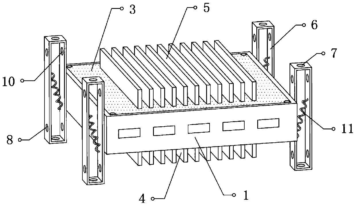
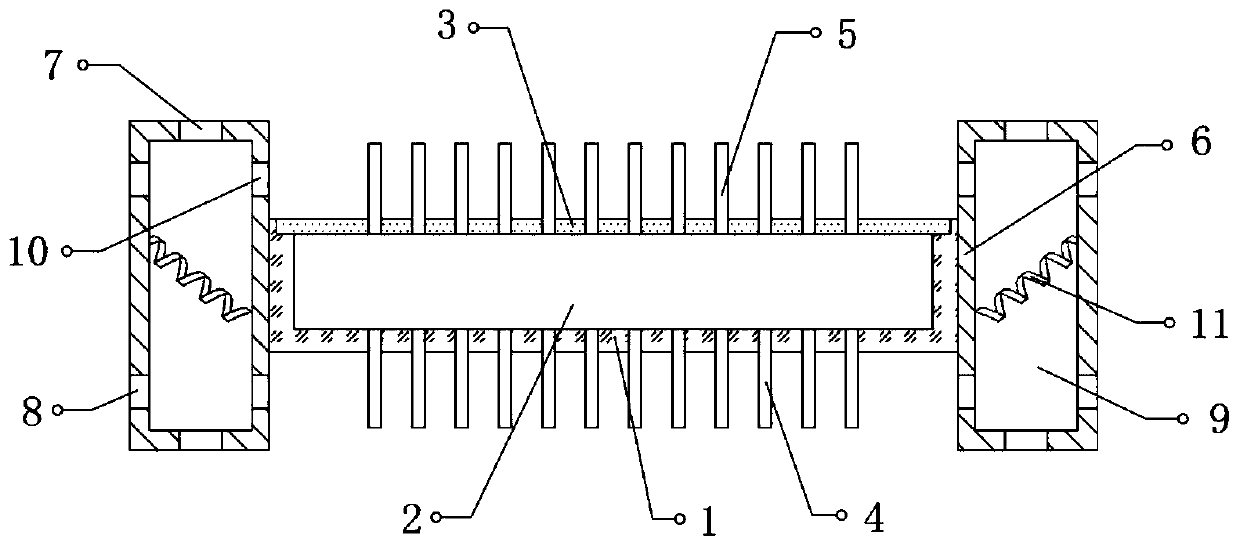
[0023] Reference Figure 1-2 , A fixing device for a computer network automatic control system, including a mounting box 1, a mounting cavity 2 is opened on the top of the mounting box 1, and corresponding electronic components and circuits are arranged inside the mounting cavity 2, and the top of the mounting cavity 2 is fixed with Cover 3, and the top outer wall of the cover 3 is fixed with second heat sinks 5 distributed equidistantly, the bottom outer wall of the installation box 1 is fixed with first heat sinks 4 distributed equidistantly, and both ends of the outer walls of the installation box 1 The fixing frame 6 is fixed, and the top and bottom outer walls of the fixing frame 6 are provided with fixing holes 7. The bottom and the top of the fixing frame 6 respectively extend beyond the first heat sink 4 and the second heat sink 5, and the fixing frame 6 is away from the installation box Mounting holes 8 are provided on the top and bottom of the outer wall on one side of...

Embodiment 2

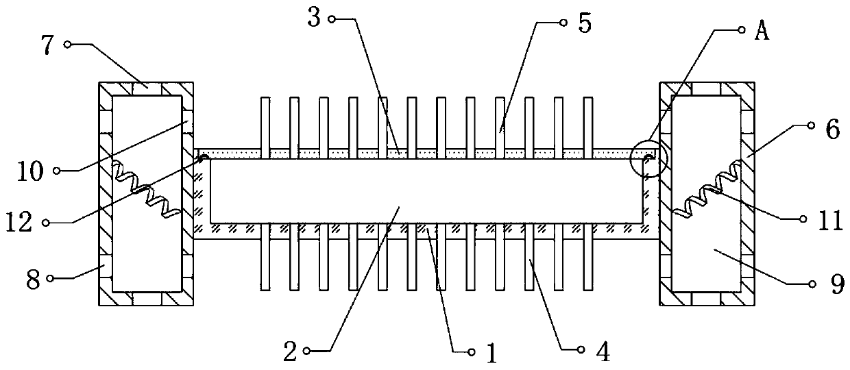
[0029] Reference figure 1 with Figure 3-4 , A fixing device for a computer network automatic control system, the two ends and both sides of the top outer wall of the installation box 1 are fixed with connecting strips 12, and the bottom outer wall of the cover plate 3 and the connecting strip 12 are provided with matching connections For the groove 13, the cross section of the connecting bar 12 is a semicircular structure, and the top of the connecting bar 12 is an arc-shaped structure, and the connecting bar 12 is made of a thermally expanded material.

[0030] Further, the device is provided with connecting strips 12 on both ends and both sides corresponding to the cover plate 3 at the top of the mounting box 1, and a matching connecting groove 13 is provided at the position corresponding to the connecting strip 12 at the bottom of the cover plate 3 to increase The airtightness between the cover plate 3 and the mounting box 1 improves the effect of moisture and dust prevention...


PUM


Abstract

The invention discloses a fixing device of a computer network automatic control system. The fixing device comprises a mounting box. A mounting cavity is formed in the top of the mounting box, and corresponding electronic elements and circuits are arranged in the mounting cavity. A cover plate is fixed at the top of the mounting cavity, and second cooling fins distributed at equal intervals are fixed to the top outer wall of the cover plate. First cooling fins distributed at equal intervals are fixed to the bottom outer wall of the mounting box. Fixing frames are fixed at the two ends of the outer walls of the two sides of the mounting box respectively, and fixing holes are formed in the top and bottom outer walls of the fixing frames respectively. The bottoms and tops of the fixing framesexceed the first cooling fins and the second cooling fins respectively. When a controller is fixed through the fixing holes in the tops or bottoms of the fixing frames, the surface of the controller cannot be attached to the inner wall of the machine. Therefore, the cooling fins can be fully utilized for cooling the controller, the cooling effect is improved, normal work of the internal electronicelements is guaranteed, and the service life of the equipment is prolonged.

Description

Technical field [0001] The invention relates to the technical field of controller fixing, in particular to a fixing device of a computer network automatic control system. Background technique [0002] Computer network refers to the connection of multiple computers with independent functions in different geographical locations and their external equipment through communication lines. Under the management and coordination of network operating systems, network management software and network communication protocols, resource sharing and information are realized The simple definition of the delivered computer system is a collection of interconnected, autonomous computers for the purpose of sharing resources. With the continuous development of computer networks, more and more automated or semi-automated production processes will be used To the computer network. [0003] The computer network automatic control system used in the actual production process is composed of multiple computer ...

Claims


Application Information

Patent Timeline
Patent Type & Authority Applications(China)
IPC IPC(8): H05K7/20H05K5/02H05K5/06
CPCH05K5/0204H05K5/069H05K7/20409
Inventor 麦瑞聪
Owner 麦瑞聪
Why Eureka
Try Eureka