Mid-infrared medical optical fiber

An infrared laser and optical fiber technology, applied in optics, light guide, medical science, etc., can solve the problems of insufficient flexibility, unusable, and inconvenient use of the articulated arm.

Inactive Publication Date: 2019-12-03
北京华夏光谷光电科技有限公司
View PDF5 Cites 1 Cited by
  • Summary
  • Abstract
  • Description
  • Claims
  • Application Information

AI Technical Summary

Problems solved by technology

But the disadvantage is that this kind of joint arm is not flexible enough, it is inconvenient to use, and because of the limitation of its volume and structure, it cannot be used to enter the human body for various mid-infrared laser surgeries or treatments.

Method used


Image

  • Mid-infrared medical optical fiber
  • Mid-infrared medical optical fiber

Examples


Embodiment Construction

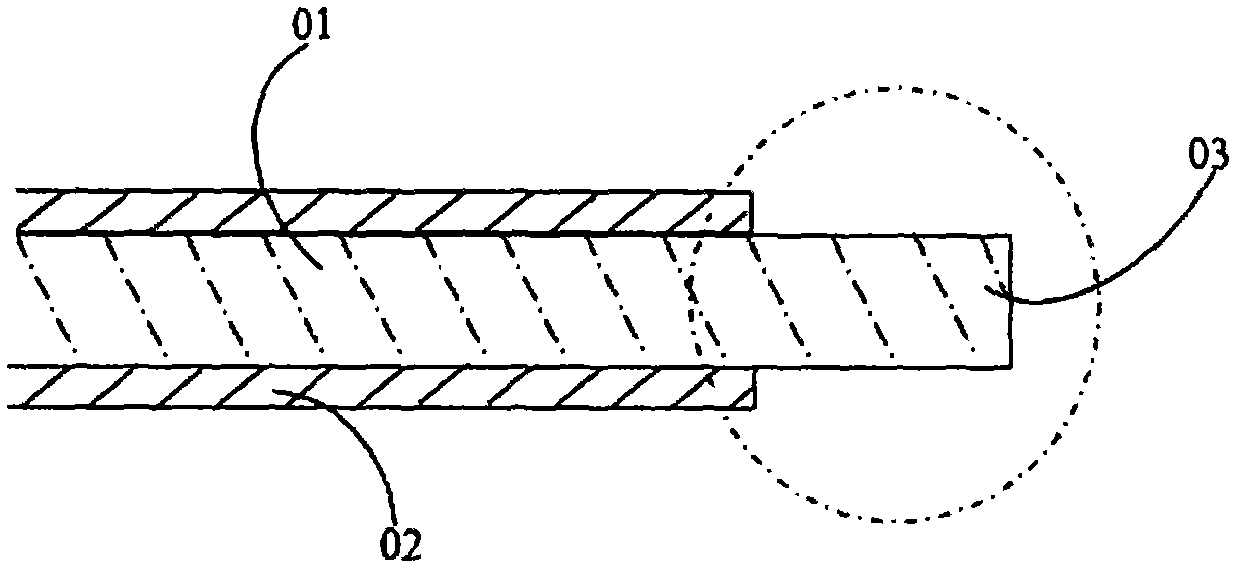
[0012] figure 1 It is a schematic diagram of medical optical fibers commonly used now. Among them, 01 is the pass-through fiber core of the optical fiber. For near-infrared or visible light and near-ultraviolet laser wavelengths below 2.2 microns, the common material is quartz (silicon dioxide). 02 is the sheath of the optical fiber, which is generally made of plastic materials. The selection of plastic materials should take into account its mechanical strength, flexibility and should be directly and safely applied to the inside of the human body. The typical material is Teflon, or other polyester materials. 03 marks the end of the optical fiber, and the fiber core 01 is exposed to a short section of the sheath, with a length of about several millimeters. The end of the optical fiber core 01 is generally cut into a right-angled plane as shown by a special cutting tool. The end surface of the optical fiber core 01 may also form a plane with a certain oblique angle with the f...


PUM


Abstract

The invention discloses a laser optical fiber suitable for mid-infrared medical treatment. The laser optical fiber can meet the requirements of safe use in the human body, can transmit lasers with mid-infrared wavelengths, and is used for various therapeutic and surgical purposes.

Description

technical field [0001] Medical optical fiber for transmitting mid-infrared laser light, which can be safely used for laser therapy and surgery entering the human body. Background technique [0002] For clinical applications, irradiate laser light to the desired in vitro or in vivo diagnosis and treatment of surgical sites. [0003] The output end of the laser fiber can be made into various shapes according to the needs, such as a spherical shape to adjust the divergence angle of the emitted laser beam, a bevel shape to make the laser emit to a certain side, a tapered or wedge shape so that the fiber can reach the soft tissue Enter etc. [0004] The commonly used silica silica optical fiber has good light transmittance to ultraviolet light below 1.06 microns or even 300 nanometers, and has a sufficiently high damage threshold. If special control is made on the core manufacturing process to reduce the concentration of OH roots in the fiber silica material, the fiber can have...

Claims


Application Information

Patent Timeline
Patent Type & Authority Applications(China)
IPC IPC(8): A61B18/22A61N5/067G02B6/44
CPCA61B18/22A61B2018/2205A61B2018/2222A61N5/0601A61N5/0613A61N5/067G02B6/44G02B6/443
Inventor 杜大勇侯晓帆刘京郊韩龙
Owner 北京华夏光谷光电科技有限公司
Why Eureka
Try Eureka