Non-contact intelligent card manufacturing equipment

A non-contact smart card and manufacturing equipment technology, which is applied to record carriers, instruments, and computer parts used in machines. It can solve the problems of chip welding, open circuit, and inaccurate placement of chips, so as to improve work efficiency and improve welding accuracy. , the effect of improving production quality

Pending Publication Date: 2019-12-03
广州明森合兴科技有限公司
View PDF1 Cites 2 Cited by
  • Summary
  • Abstract
  • Description
  • Claims
  • Application Information

AI Technical Summary

Problems solved by technology

In this process, since the PVC sheet is processed by winding first, then the chip to be welded is transported to the place where the chip of each PVC winding card in the PVC winding card unit on the PVC sheet is to be welded, and then the chip is processed. Welding with PVC winding card, therefore, when some factors (such as vibration, wind) cause the chip to deviate from the chip welding position in the PVC sheet, so th

Method used


Image

  • Non-contact intelligent card manufacturing equipment
  • Non-contact intelligent card manufacturing equipment
  • Non-contact intelligent card manufacturing equipment

Examples


Embodiment 1

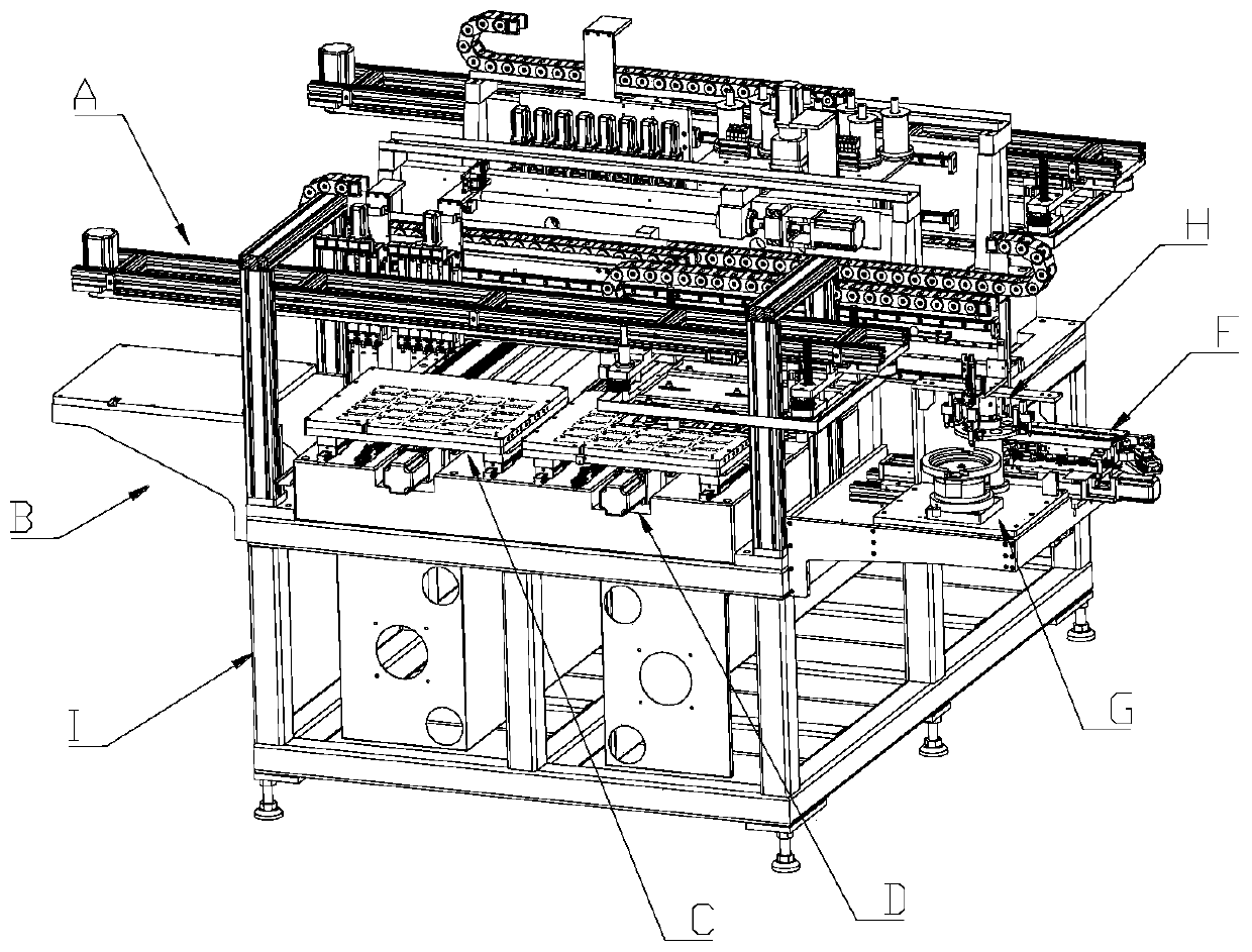
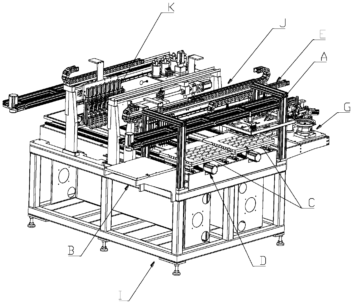
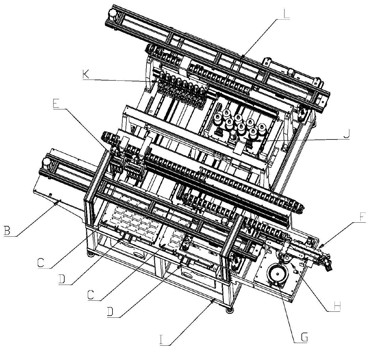
[0051] see Figure 1-Figure 42 , the non-contact smart card manufacturing equipment of the present invention comprises a rack I, a sheet feeding device arranged on the rack I, a chip feeding device, a winding device J, a chip welding device K, and a sheet feeding device in the sheet feeding device. The sheet material 7a and the chips in the chip feeding device are sequentially conveyed to the conveying devices in the winding device J and the chip bonding device K, wherein,

[0052] The conveying device includes two positioning platforms C arranged on the frame I for precise positioning of the sheet material 7a and the chips, and a conveying mechanism D for driving the two positioning platforms C to move independently, wherein the The two positioning platforms C are arranged in parallel, and each positioning platform C is driven by a single conveying mechanism D;

[0053] The chip feeding device includes a chip placing table G and a second conveying device E for transferring t...

Embodiment 2

[0142] see Figure 43 The difference between this embodiment and Embodiment 1 is that the vertical drive assembly of the positioning assembly 5a in the first conveying device A in this embodiment can also be in another form, and the vertical drive assembly includes a slider sliding rail mechanism and the spring 5-4a; wherein the slider rail mechanism includes a positioning guide rail 5-5a and a positioning slider 5-6a matching with the positioning guide rail 5-5a; the guide rail The upper end of the slide rail is connected with the mounting frame 2a, the positioning member 5-1a is fixed on the lower end of the positioning slider 5-6a through the connecting member 5-7a, and the lower part of the positioning guide slide rail 5-5a is also provided with a At the limiting portion 5-21a that defines the position of the positioning slider 5-6a, the spring 5-4a is arranged between the mounting frame 2a and the positioning slider 5-6a, and one end of the spring 5-4a is It acts on the ...

Embodiment 3

[0144] see Figure 44 , the difference between this embodiment and Embodiment 1 and Embodiment 2 is that the first vertical driving mechanism 6a in the first conveying device A in this embodiment may be in another form, and the screw rod 6- 3a The transmission assembly is a group, the first driven driving wheel 6-6a is arranged on the vertical fixing seat 6-2a, and a guide is provided between the mounting frame 2a and the vertical fixing seat 6-2a. A guide post and guide sleeve mechanism for the mounting frame 2a to move up and down, wherein the guide post and guide sleeve mechanisms are in multiple groups, and the multiple groups of guide post and guide sleeve mechanisms are distributed around the mounting frame 2a; The mechanism includes a guide post 6-9a and a guide sleeve 6-10a matched with the guide post 6-9a. One end of the guide sleeve 6-10a is fixed on the vertical fixing seat 6-2a. One end of -9a is fixed on the mounting frame 2a, and the other end extends vertically...


PUM


Abstract

The invention discloses non-contact intelligent card manufacturing equipment. The non-contact intelligent card manufacturing equipment comprises a rack, and comprises a plate feeding device, a chip feeding device, a winding device, a chip welding device and a conveying device which are arranged on the rack. The conveying device comprises a positioning platform and a conveying mechanism. The positioning platform comprises a base plate and a plurality of wire wrap card positions arranged on the base plate. The wire wrap card positions are in one-to-one correspondence with the wire wrap card units on the plate; each wire wrap card position is provided with a chip storage groove, and the chip storage grooves are in one-to-one correspondence with chip placement positions in the wire wrap card units. The plate feeding device comprises a plate containing table and a first carrying device. The chip feeding device comprises a chip placing table and a second carrying device. According to the non-contact intelligent card manufacturing equipment, accurate positioning of the plate and the chip in the production process of a non-contact intelligent card can be achieved, and therefore the production quality and the production efficiency of the non-contact intelligent card are improved.

Description

technical field [0001] The invention relates to a smart card manufacturing device, in particular to a non-contact smart card manufacturing device. Background technique [0002] In the production process of non-contact smart card, the following processing steps are usually required: laser drilling process, wire winding process, chip welding process, ultrasonic composite welding process and cutting process; after the above processing processes, an independent The smart card board unit provides semi-finished raw materials for subsequent processing. [0003] Existing smart card winding equipment, for example, the invention patent application with application publication number CN108000909A discloses "a contactless smart card manufacturing production line". Sheet mounting frame for rolls, laser drilling module, smart card winding processing module, chip welding device K, ultrasonic composite welding module, pulling module for pulling and conveying PVC sheet and PVC covering shee...

Claims


Application Information

Patent Timeline
IPC IPC(8): B29C65/02B29C65/78B29C37/00G06K19/077
CPCB29C65/02B29C65/7808B29C65/7855G06K19/077
Inventor 王开来赖汉进卢国柱吴伟文席道友
Owner 广州明森合兴科技有限公司
Why Eureka
Try Eureka