Machine gun mounting and driving structure for unmanned aerial vehicle

A driving structure and UAV technology, applied in the UAV field, can solve problems such as low launch speed, no reference provided, barrel withdrawal, etc., achieve high reliability and safety, improve control safety, structure simple and reliable effect

Active Publication Date: 2019-12-03
CHINA NATIONAL AERO-TECHNOLOGY IMPORT & EXPORT CORPORATION +1
View PDF18 Cites 3 Cited by
  • Summary
  • Abstract
  • Description
  • Claims
  • Application Information

AI Technical Summary

Problems solved by technology

From the point of view of the structure of the connected weapon provided by this prior art, it only provides a small cylinder to be sleeved on the gun barrel. Whether the connection is firm or not, and how the stability of the connection seems to be a big problem, and this prior art There is also no mention of how to keep the barrel from exiting the small cylinder in case of recoil
In addition, the preferred weapon of this prior art is a grenade launcher with a low rate of fire, and the reliability of the connection structure is not high, so the connection structure provided by it is not suitable for a machine gun with a high rate of fire and a large recoil
[0005] In short, most of the mounted weapons provided by the existing armed drones need to be specially designed, the reliability and cost are difficult to control, and it is difficult to convince customers to accept the newly designed weapons
And the prior art does not provide a structure for reference that can mount existing mature weapons such as machine guns
[0006] In addition, the above prior art does not disclose any technical solutions related to the manipulation of the machine gun mounted on the drone

Method used


Image

  • Machine gun mounting and driving structure for unmanned aerial vehicle
  • Machine gun mounting and driving structure for unmanned aerial vehicle
  • Machine gun mounting and driving structure for unmanned aerial vehicle

Examples


Embodiment Construction

[0030] In order to have a clearer understanding of the technical features, purposes and effects of the present application, specific implementation methods of the present application will now be described with reference to the accompanying drawings. Wherein, the same parts adopt the same reference numerals.

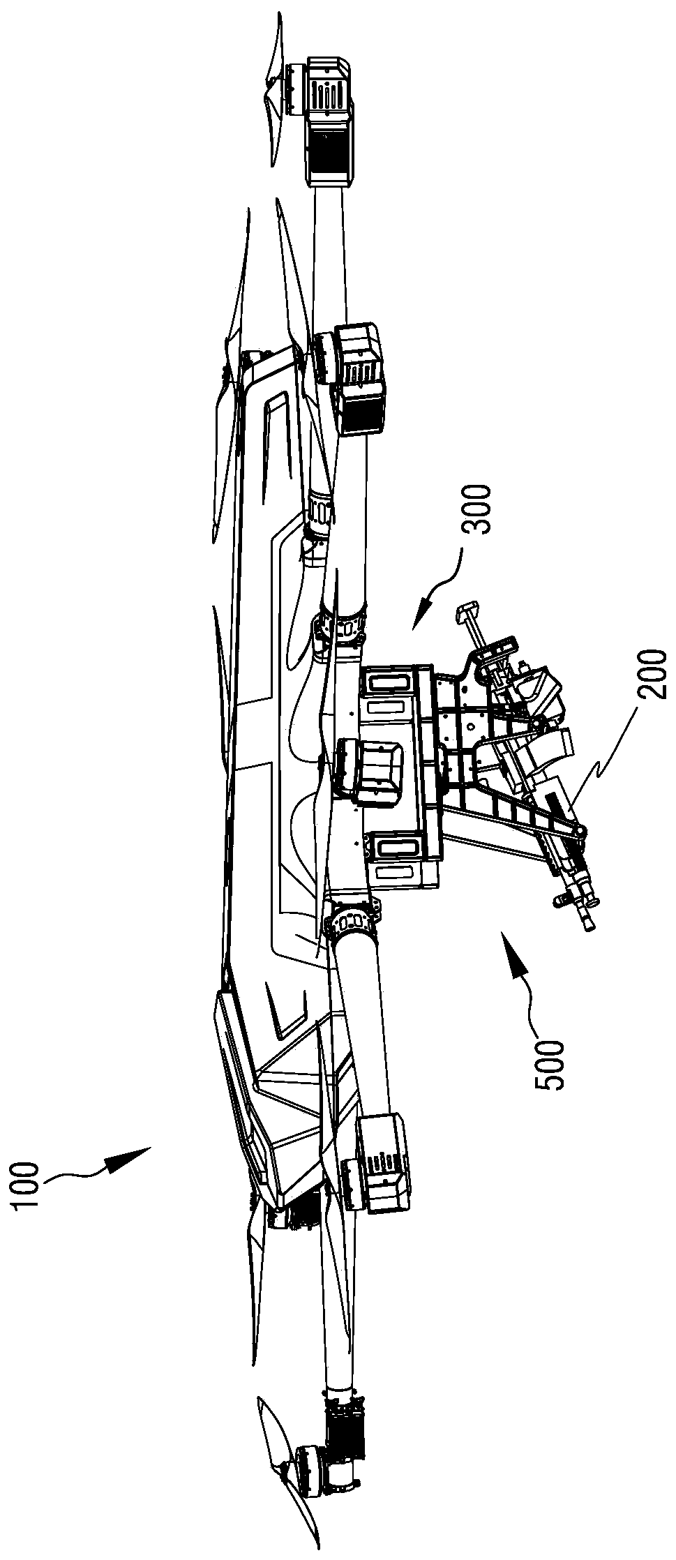
[0031] Such as figure 1 Shown is a schematic structural diagram of a UAV 100 with a machine gun mounted thereon according to a specific embodiment of the present application. The present application provides a machine gun pylon 500 that can be used to mount a machine gun 200 under the UAV 100. The machine gun pylon 500 can be directly connected to the belly of the UAV 100, or as figure 1 As shown, it is mounted under the UAV 100 through an extension hanger 300 . The UAV 100 shown in the figure is a multi-rotor UAV. Of course, those skilled in the art should understand that the UAV 100 is not limited to a rotorcraft, it can also be a fixed-wing UAV, and it can be an oil-...


PUM


Abstract

The invention provides a machine gun mounting and driving structure. The machine gun mounting and driving structure comprises a machine gun hanging rack, a safety driving mechanism and a trigger driving mechanism. According to the machine gun hanging rack, a front bolt, a middle bolt and a tail spacing frame are adopted to clamp a machine gun, so that the structure is simple and reliable, and themachine gun can be easily detached or fixed on an unmanned aerial vehicle. The safety driving mechanism can remotely control stretching and retracting of a linear motor so as to operate and control asafety of the machine gun mounted on the unmanned aerial vehicle, so that locking or unlocking of the machine gun is realized; and the safety driving mechanism is simple to operate, accurate in travelpositioning, and rapid in action and capable of improving operation safety when the machine gun is mounted on the unmanned aerial vehicle. The trigger driving mechanism can remotely control power-onand power-off of an electromagnet so as to operate and control a trigger of the machine gun mounted on the unmanned aerial vehicle, so that firing and fire holding of the machine gun can be realized;and meanwhile operation and control are simple, and prevention measures for preventing jamming are provided so that safety accidents of difficulties in firing and fire holding are avoided, in this way, high reliability and safety can be achieved.

Description

technical field [0001] The present application relates to the technical field of unmanned aerial vehicles, in particular to an armed unmanned aerial vehicle with weapons, and in particular to a machine gun mounting and driving structure for an unmanned aerial vehicle. Background technique [0002] Unmanned aircraft, referred to as "UAV", is an unmanned aircraft controlled by radio remote control equipment and its own program control device. According to the application field, UAV can be divided into military and civilian. In terms of military use, drones are divided into reconnaissance drones, target drones, and armed drones that have become popular in recent years. Civilian drones are widely used in aerial photography, agriculture, plant protection, micro-selfies, express delivery, disaster relief, observation of wild animals, monitoring of infectious diseases, surveying and mapping, news reports, power inspections, disaster relief, film and television shooting and other f...

Claims


Application Information

Patent Timeline
IPC IPC(8): B64D7/02F41A17/06
CPCB64D7/02F41A17/06
Inventor 朱颖王达权鑫赵学松宗宁庞振岳曹庆旭
Owner CHINA NATIONAL AERO-TECHNOLOGY IMPORT & EXPORT CORPORATION
Why Eureka
Try Eureka