Sponge city drainage structure and sponge city water circulating method

A drainage structure and sponge city technology, applied in drainage structures, water/sewage treatment, general water supply conservation, etc., can solve the problem of low utilization rate of rainwater on urban roads, and achieve the goal of improving utilization rate, saving water resources, and high permeability Effect

Inactive Publication Date: 2019-12-03
广东洋艺建设有限公司
View PDF5 Cites 17 Cited by
  • Summary
  • Abstract
  • Description
  • Claims
  • Application Information

AI Technical Summary

Problems solved by technology

At the same time, the rainwater directly enters the urban drainage pipes and i

Method used


Image

  • Sponge city drainage structure and sponge city water circulating method
  • Sponge city drainage structure and sponge city water circulating method
  • Sponge city drainage structure and sponge city water circulating method

Examples


Embodiment Construction

[0036] The present invention will be described in further detail below in conjunction with the accompanying drawings.

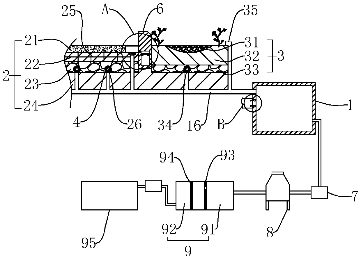
[0037] refer to figure 1 , is a sponge city drainage structure disclosed by the present invention, comprising a sump 1, a road layer structure 2 and a green belt 3, and the road structure sequentially includes a permeable concrete layer 21, a mortar leveling layer 22, and a graded crushed stone layer from top to bottom 23 and the plain soil layer 24, the mortar leveling layer 22 is provided with a support grid 25, the thickness of the graded crushed stone layer 23 is 50 mm, and the graded crushed stone layer 23 uses graded crushed stone as aggregate, and the maximum crushed stone The particle size does not exceed 40mm. A diversion tube 26 is placed in the graded gravel layer 23, the diameter of the diversion tube 26 is not more than 30 mm, and the side wall of the diversion tube 26 is provided with a through hole (not shown), and the side wall of the diversi...


PUM


Abstract

The invention relates to a sponge city drainage structure and a sponge city water circulating method. A road structure comprises a permeable concrete layer, a mortar leveling layer, a graded broken stone layer and a plain soil layer from top to bottom in sequence; support grids are arranged in the mortar leveling layer; a guide pipe for drainage is arranged in the graded broken stone layer; drainage ditches and road traffic stones are arranged on the two sides of the road layer structure; the drainage ditches are positioned between the road layer structure and the road traffic stones; drain pipes are arranged at the bottoms of the drainage ditches; water storage cavities are formed in the road traffic stones, and communicate with the drainage ditches through drainage holes; the other sides, relative to the drainage holes, of the water storage cavities communicate with green belts through permeable holes; the green belts comprise pebble beds, planting soil layers and green broken stonelayers in sequence from top to bottom; drainage pipes for drainage are arranged in the green broken stone layers; a water collecting pool is connected with a main pipe; and the guide pipe, the drain pipes and the drainage pipes communicate with the main pipe. The structure achieves the effects of reducing the city road ponding conditions and improving the rainwater utilization rate.

Description

technical field [0001] The invention relates to the technical field of sponge cities, in particular to a sponge city drainage structure and a sponge city water circulation method. Background technique [0002] Sponge city is to build the city into a sponge-like body that can absorb, store, infiltrate and purify water, resolve natural disasters caused by rainwater, and make it a water-elastic city that can be retracted freely. The construction of a sponge city is not to overthrow and replace the traditional drainage system, but to reduce and supplement the traditional drainage system, and to maximize the role of the urban water supply and drainage network itself. [0003] Traditional road construction relies on ordinary bricks or concrete paving. When it rains, the bricks and concrete do not absorb or seep water. The road surface is wet and slippery. The drainage of rainwater depends on urban drainage pipes. Often due to heavy rain, heavy rain, large displacement, and blocka...

Claims


Application Information

Patent Timeline
IPC IPC(8): E01C7/32E01C11/22E01F5/00E03B3/02E03F5/10E03F5/14C02F9/02
CPCC02F1/001C02F1/283C02F1/38C02F9/00C02F2001/007C02F2103/001C02F2301/08E01C7/32E01C11/226E01C11/227E01F5/00E03B3/02E03F5/10E03F5/14Y02A20/108
Inventor 刘宋祥
Owner 广东洋艺建设有限公司
Why Eureka
Try Eureka