Power station boiler waste heat utilization system based on inlet flue gas temperature communication control

A waste heat and flue gas technology, applied in the field of power station boiler waste heat utilization system based on the communication control of inlet flue gas temperature, can solve the problems of affecting the efficiency of heat exchange, lack of intelligent control, and decrease in heat exchange capacity, and achieve smooth flow. , to avoid uneven segmentation, inhibit the effect of backflow

Active Publication Date: 2019-12-03
SUZHOU HAILU HEAVY IND
View PDF7 Cites 4 Cited by
  • Summary
  • Abstract
  • Description
  • Claims
  • Application Information

AI Technical Summary

Problems solved by technology

During the evaporation process of the heat pipe, it will inevitably carry liquid to the steam end. At the same time, because of the exothermic condensation of the condensation end, there will be liquid in the condensation end, and the liquid will inevitably mix with the steam, so that the fluid in the heat pipe is vapor. Liquid mixture, the existence of vapor-liquid mixture causes the gas to mix together, and the heat exchange capacity between the liquid and the liquid decreases, which greatly affects the heat exchange efficiency
[0005] In the boiler waste heat utilization system of the prior art, there is a lack of research on intelligent control, especially the intelligent control when there are multiple waste heat utilization equipment at the same time, such as setting heat distribution, etc.

Method used


Image

  • Power station boiler waste heat utilization system based on inlet flue gas temperature communication control
  • Power station boiler waste heat utilization system based on inlet flue gas temperature communication control
  • Power station boiler waste heat utilization system based on inlet flue gas temperature communication control

Examples


Embodiment Construction

[0043] The specific embodiments of the present invention will be described in detail below with reference to the accompanying drawings.

[0044] In this article, if there are no special instructions, when it comes to formulas, " / " means division, and "×" and "*" mean multiplication.

[0045] The specific embodiments of the present invention will be described in detail below with reference to the accompanying drawings.

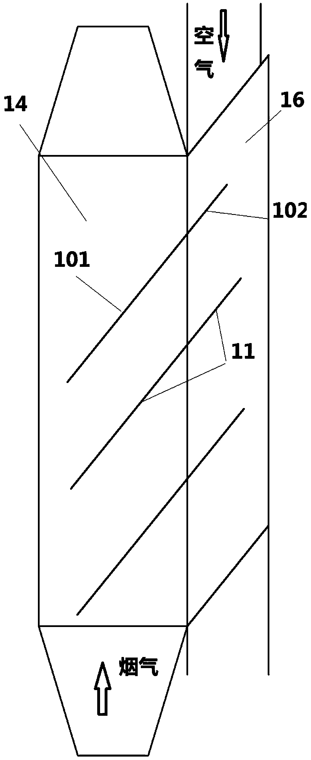
[0046] A power plant boiler flue gas waste heat utilization system. The waste heat utilization system includes an air preheater 1. The air preheater 1 includes a heat pipe 10, a flue gas channel 14 and an air channel 16, and the heat pipe 10 includes an evaporation An end 101 and a condensation end 102, the condensation end 102 is arranged in the air channel 12, and the evaporation end 101 is arranged in the flue. The evaporation end 101 absorbs the waste heat of the flue gas in the boiler flue, and transfers the heat to the air in the air passage 12 through the cond...


PUM


Abstract

The invention provides a power station boiler waste heat utilization system capable of intelligently controlling and utilizing waste heat. The system comprises an air preheater and a heat accumulator,the system further comprises a central controller. The central controller is in data connection with an air preheater valve and a heat accumulator valve, a third temperature sensor is arranged at theposition of a flue gas inlet of the air preheater, and the central controller automatically controls the valve opening of the air preheater valve and the valve opening of the heat accumulator valve according to the temperature detected by the third temperature sensor. Through the operation, when the temperature of flue gas is high and the generation requirement of preheated air is met, redundantheat is stored through the heat accumulator, and when the temperature of the flue gas is low, more flue gas can enter the air preheater to be used for preheating the air, so that the requirement of the preheated air is met, and meanwhile, energy is saved.

Description

Technical field [0001] The present invention is part of a subject project jointly researched and developed with an enterprise. It is an improvement to the previous application, and relates to the field of heat pipe waste heat recovery, and in particular to a method and device for controlling waste heat recovery of flue gas using heat pipes. Background technique [0002] With the rapid economic development of our country, energy consumption is increasing, and the problem of deteriorating urban air quality has become more and more prominent. The problems of saving energy and reducing the emission of environmental harmful substances are urgent. In the common steam generation process, one of the main reasons for high energy consumption and serious pollution is that the exhaust temperature of the boiler flue gas is too high, which wastes a lot of energy. Therefore, the waste heat of the boiler exhaust gas is recovered and reused to achieve energy saving and emission reduction. Purpose...

Claims


Application Information

Patent Timeline
Patent Type & Authority Applications(China)
IPC IPC(8): F23L15/04F23N3/00F23N3/06F28D15/04F28D21/00
CPCF23L15/04F23L2900/15043F23N3/002F23N3/06F23N2900/05005F28D15/046F28D21/001Y02E20/34
Inventor 王逸隆马军江程李言伟连根款
Owner SUZHOU HAILU HEAVY IND
Why Eureka
Try Eureka