Universal industrial alarm circuit and control method thereof
A control method and alarm technology, applied in the electronic field, can solve the problems of many drive units, unfavorable management and maintenance, high-frequency interference, etc.
- Summary
- Abstract
- Description
- Claims
- Application Information
AI Technical Summary
Problems solved by technology
Method used
Image

Examples
Embodiment 1
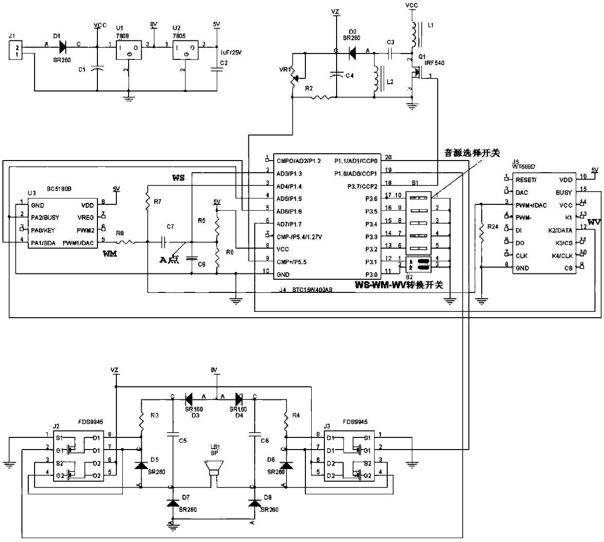
[0044] See attached figure 1 As shown, a general-purpose industrial alarm circuit includes: a control unit, an amplification unit, a drive unit and a power supply unit;
[0045] The output port of the drive unit is connected to the input port of the control unit, the output port of the control unit is connected to the amplification unit, and the power supply unit is connected to the control unit;
[0046] The control unit is used to generate a PWM signal and control the driving unit to boost or lower the voltage. The driving unit is used to output the working voltage to the amplifying unit. The amplifying unit is used to amplify the PWM signal. The power supply unit is used to supply power to the control unit.
[0047] In a specific embodiment, the power supply unit includes: a diode D1, a voltage regulator U1, a voltage regulator U2, a capacitor C1, and a capacitor C2;
[0048] The anode of diode D1 is connected to port 2 of plug J1, port 1 of plug J1 is connected to one end...
Embodiment 2
[0072] Take the model of the single-chip microcomputer J4 as STC15W402AS as an example, the ADC inside the single-chip microcomputer J4 has a conversion accuracy of 10 bits, and the voltage value of V2 is 5V.
[0073] Embodiment 2 discloses a general-purpose industrial siren circuit control method, including a method for generating a PWM signal and a method for controlling output volume;
[0074] The method for generating the PWM signal is realized by the control unit, and the control method for the output volume is realized by the driving unit and the amplifying unit.
[0075] In a specific embodiment, the method for generating a PWM signal includes the following steps:
[0076] S1: Let the intersection of capacitor C8 and capacitor C7 in the control unit be point A, R5 and R6 of the control unit satisfy R5=3R6, and the DC bias voltage of point A is Among them, V2 is the power supply voltage output by the voltage output terminal 2 of the power supply unit, and the AC input ...
PUM
 Abstract
Description
Claims
Application Information
 - R&D Engineer
- R&D Manager
- IP Professional
- Industry Leading Data Capabilities
- Powerful AI technology
- Patent DNA Extraction
Browse by: Latest US Patents, China's latest patents, Technical Efficacy Thesaurus, Application Domain, Technology Topic.
© 2024 PatSnap. All rights reserved.Legal|Privacy policy|Modern Slavery Act Transparency Statement|Sitemap