Roller coating unit

A technology of roller coating and unit, which is applied in the direction of coating, liquid coating device on the surface, etc. It can solve the problems of time-consuming and laborious disassembly, no operating space, and small size of positioning parts, so as to achieve easy layout, improve efficiency, work reliably

Pending Publication Date: 2019-12-06
WISDRI ENG & RES INC LTD
View PDF0 Cites 0 Cited by
  • Summary
  • Abstract
  • Description
  • Claims
  • Application Information

AI Technical Summary

Problems solved by technology

[0004] The current conventional method is to manually operate positioning parts such as bolts. Due to the small size and large number of positioning parts, it is time-consuming and laborious to complete the disassembly and assembly work in a short period of time, and the operation next to the equipment is dangerous; especially on the exit side of the 1# roller coating vehicle. There is basically no operating space for the installation of the positioning parts on the entrance side of the 2# roller coating vehicle, and manual operations beside the machine are not allowed

Method used


Image

  • Roller coating unit
  • Roller coating unit
  • Roller coating unit

Examples


Embodiment Construction

[0026] The technical solutions in the embodiments of the present invention will be described clearly and completely below. Obviously, the described embodiments are only a part of the embodiments of the present invention, rather than all the embodiments. Based on the embodiments of the present invention, all other embodiments obtained by those of ordinary skill in the art without creative efforts shall fall within the protection scope of the present invention.

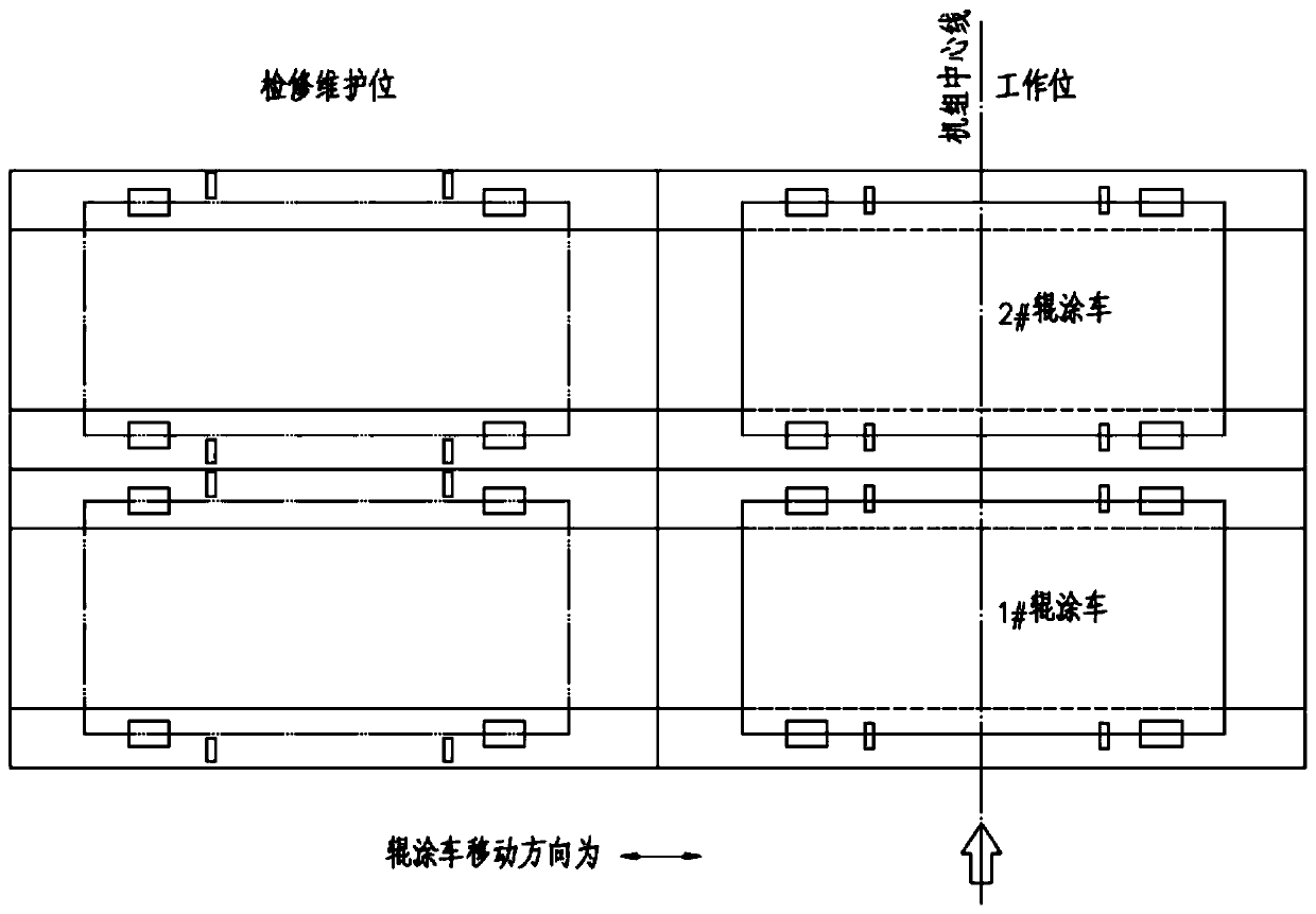
[0027] The embodiment of the present invention provides a roller coating unit, which includes a plurality of roller coating vehicles 9 arranged in series along the running direction of the strip steel. The specific structure of the vehicle 9 is not repeated here. At least one set of positioners for locking the roller coating car 9 is respectively provided between every two adjacent working positions and between every two adjacent maintenance positions, and more preferably, multiple sets are provided, so that between two...


PUM


Abstract

The invention relates to a roller coating unit. A positioning machine is used for implementing locking and unlocking of a roller coating trolley; the positioning machine comprises a double-surface inclined wedge block, a guide slide way, a positioning base and a positioning part, wherein the positioning base is slidably arranged on the guide slide way; the positioning part is arranged at the frontend of the positioning base; the positioning base is provided with a driven groove; the driven groove comprises two driven surfaces which are sequentially arranged in the sliding direction of the positioning base; the two driven surfaces are each of a bevel which forms an included angle with the sliding direction of the positioning base; and the two wedge surfaces of the double-surface inclined wedge block are matched with the two driven surfaces so that the positioning part is inserted into a positioning gap of the roller coating trolley or is released from the inside of the positioning gapof the roller coating trolley. The roller coating unit realizes locking and unlocking of the roller coating trolley by cooperation of the double-surface inclined wedge block and the positioning base comprising the driven grooves, can replace complicated manual assembly and disassembly of the positioning part and can effectively improve the maintenance efficiency of equipment; the positioning machine is easy to arrange, occupies a small space and can preferably adapt to the work condition that the space between adjacent roller coating machines of the roller coating unit is narrow and small, sothe labor cost is lowered and the maintenance risks are reduced.

Description

technical field [0001] The invention belongs to the technical field of metallurgical equipment, and particularly relates to a roller coating unit. Background technique [0002] Metallurgical machinery and equipment generally have the characteristics of complex structure, large volume and high precision requirements, and most of them continue to work under high temperature, heavy load, dusty and corrosive conditions; therefore, some equipment needs to be replaced frequently, such as rolls, coating rolls, bearings and many more. In particular, for equipment that requires accurate positioning and frequent replacement, safe and efficient equipment maintenance is particularly important. It is of great significance to shorten the process time, ensure product quality, and improve the economic benefits of the enterprise. At the same time, it saves a lot of manpower and reduces labor. strength. An additional maintenance station within the same equipment frame can meet such needs. ...

Claims


Application Information

Patent Timeline
Patent Type & Authority Applications(China)
IPC IPC(8): B05C1/08B05C11/00
CPCB05C1/08B05C11/00
Inventor 陈洁
Owner WISDRI ENG & RES INC LTD
Why Eureka
Try Eureka