High-strength fiber reinforced composite material connecting piece and formula and manufacturing process thereof

A technology of reinforced composite materials and high-strength fibers, applied in the direction of coating, etc., can solve the problems of easy breakage of connectors, poor pullout ability, poor heat insulation performance, etc., to enhance the pullout force, reduce the possibility of breaking free, and prevent The effect of improving the combustion performance

Pending Publication Date: 2019-12-06
山东联强建筑工业科技有限公司
View PDF0 Cites 1 Cited by
  • Summary
  • Abstract
  • Description
  • Claims
  • Application Information

AI Technical Summary

Problems solved by technology

[0004] The purpose of the present invention is to solve the problems of easy breakage, poor drawing ability, poor heat insulation performance and short service life of the connectors caused by defects in the structure, formula and process between the insulation layer and the wall. A high-strength fiber-reinforced composite connector and its formulation and manufacturing process are proposed

Method used


Image

  • High-strength fiber reinforced composite material connecting piece and formula and manufacturing process thereof
  • High-strength fiber reinforced composite material connecting piece and formula and manufacturing process thereof
  • High-strength fiber reinforced composite material connecting piece and formula and manufacturing process thereof

Examples


Embodiment 1

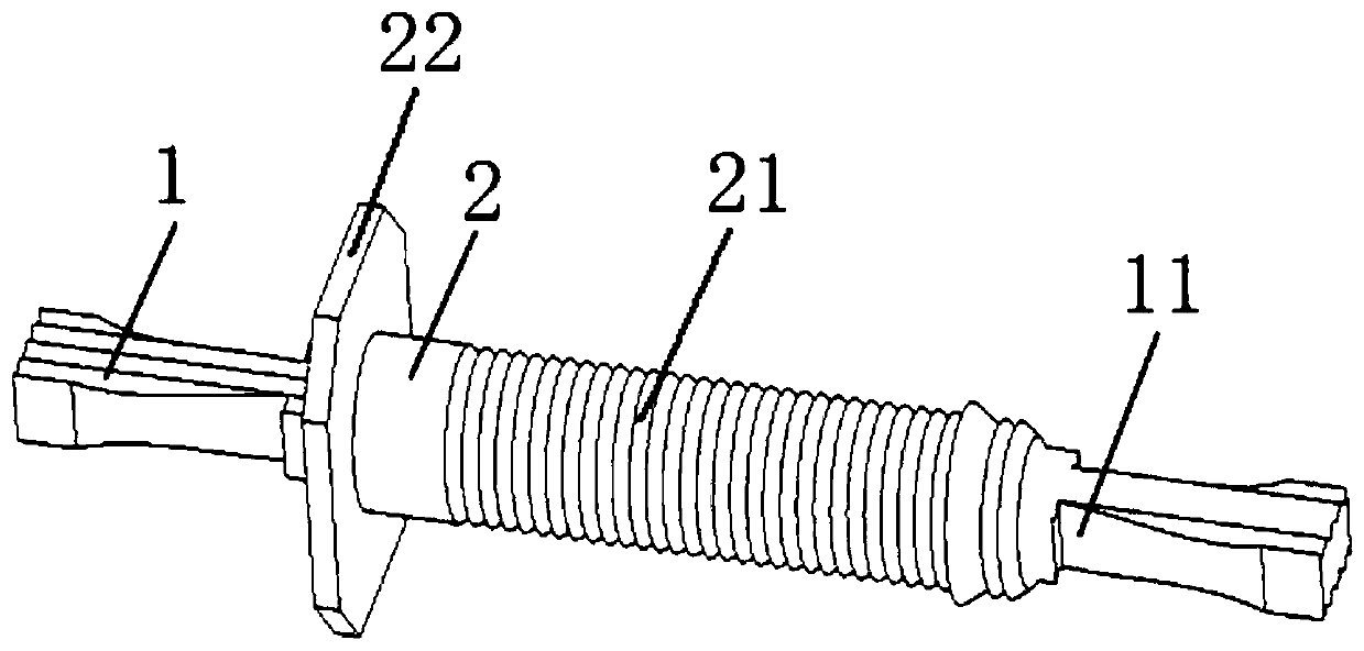
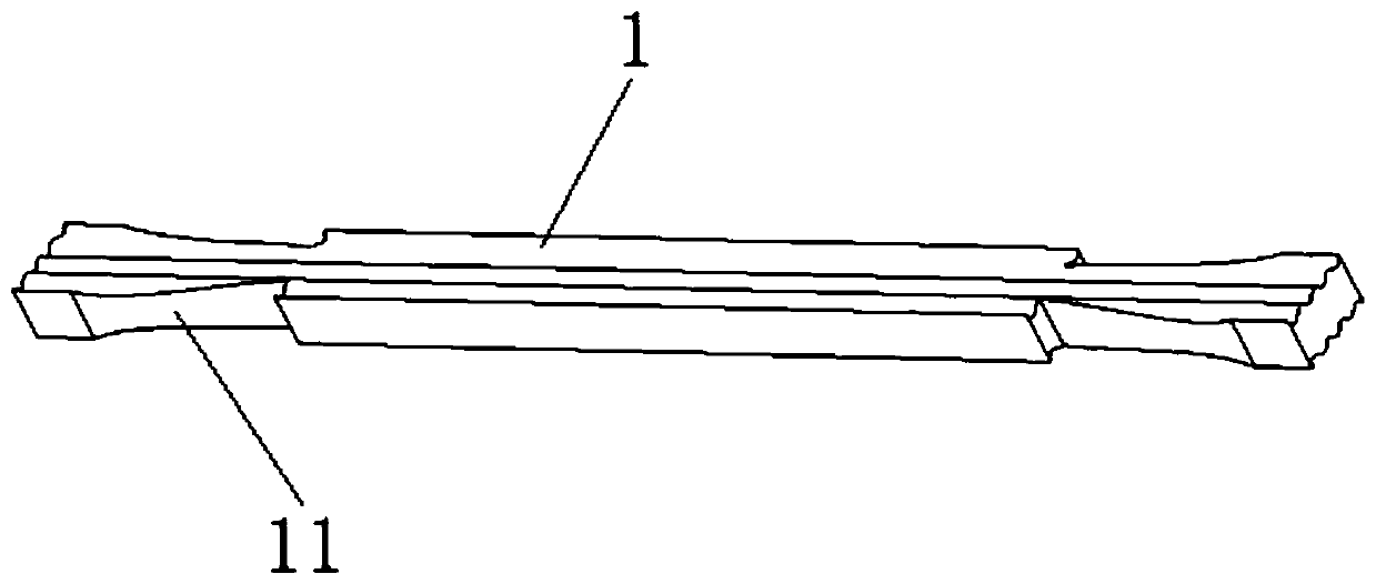
[0045] The high-strength fiber-reinforced composite material connector in this embodiment includes an anchoring fiber rod 1 and an injection-molded intermediate body 2. The anchoring fiber rod 1 is in the shape of a flat strip, and its cut surface is wavy, such as figure 2 As shown, since the top surface and the bottom surface of the anchoring fiber rod 1 are not flat, they are all set as wavy surfaces, so the cut surface has a wavy shape. Of course, the two sides of the anchoring fiber rod 1 can also be set as wavy surfaces, so that the four sides of the cut surface will all be wavy. The anchoring fiber rod 1 is also provided with two symmetrical dovetail grooves 11 at the ends of two opposite sides. The anchoring fiber rod 1 is designed to have a wave surface and a dovetail groove 11, which can greatly increase the contact surface between the anchoring fiber rod 1 and the cement, increase friction and fastening force, and the special-shaped surface can bring stronger anchor...

Embodiment 2

[0058] The injection molding intermediate 2 of this embodiment has the same structure as that of the injection molding intermediate 2 of Embodiment 1, except that the anchoring fiber rod 1 of this embodiment is cylindrical or elliptical, and its cut surface is petal-shaped or five-pointed star-shaped. Since the surface of the anchoring fiber rod 1 is not a smooth curved surface, but has protrusions and depressions, its cutting surface is petal-shaped or five-pointed star-shaped. Moreover, a number of lock grooves 12 are uniformly arranged on the axial surface thereof.

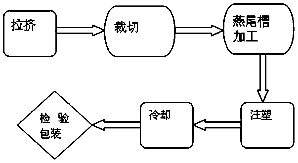
[0059] The formulation of the anchoring fiber rod and the injection molding intermediate in this embodiment are the same as in Embodiment 1, but the manufacturing process of the connecting piece is different. The process steps of this embodiment are:

[0060] S1. Preforming: Using preforming equipment, the resin-impregnated fiber yarn is preformed into splines with petal-shaped or five-pointed star-shaped cutti...

Embodiment 3

[0069] The difference between this example and Example 1 and Example 2 is that the formulation of the anchoring fiber rod can also be composed of the following components and mass ratio: 60 parts of fiber, 15 parts of resin, 5 parts of active reinforcing filler, solidified 3 parts of agent, 2 parts of toughening agent.

[0070] Wherein, the fiber is selected from glass fiber; the resin is selected from vinyl resin or epoxy resin, the active reinforcing filler can be selected from aluminum hydroxide or calcium carbonate or talcum powder or quartz powder, etc., and the curing agent can be selected from PBO curing Paste, tert-butyl ester, etc., PE powder, etc. can be selected as the toughening agent.

[0071] The formulation of the injection molding intermediate in this embodiment can also be composed of the following components and mass ratio: 75 parts of plastic, 8 parts of activated filler, and 8 parts of fiber. Wherein, the plastic can be any one of PP, ABS, PVC, etc., the a...


PUM

PropertyMeasurementUnit
thicknessaaaaaaaaaa
diameteraaaaaaaaaa
mechanical propertiesaaaaaaaaaa

Abstract

The invention discloses a high-strength fiber reinforced composite material connecting piece and a formula and manufacturing process thereof. The connecting piece comprises an anchor fiber rod and aninjection molding intermediate body; a dovetail groove or a locking groove is formed in the anchor fiber rod; the injection molding intermediate body wraps the middle section of the anchor fiber rod;and a screw thread is disposed in the injection molding intermediate body. By changing the structures of the anchor fiber rod and the injection molding intermediate body, the contact area of the connecting piece and concrete can be greatly increased, and thus the drawing force is enhanced. The drawing force of the connecting piece can reach 15-20 kN; by changing the cross section shape of the anchor fiber rod, the stretching and bending degrees of the composite material are greatly improved; and the stretching strength of the connecting piece can reach 900-1100 MPa, and the bending strength ofthe connecting piece can reach 1000-1200 MPa.

Description

technical field [0001] The invention relates to the technical field of construction, in particular to a high-strength fiber-reinforced composite material connector and its formula and manufacturing process. Background technique [0002] The high-strength fiber-reinforced composite material connector is an intermediate used to ensure a tight connection between the insulation layer and the wall. At present, the connectors of Thermomass imported from the United States are mainly used in the market, and those produced in China also imitate the imported products. The final use is to connect the inner and outer walls and fasten the insulation layer. The structural design and production process are roughly the same. At present, there are still some defects in the design of the connectors. One is that the contact surface with the cement is not large enough, which will directly affect the pull-out force in the connection. Greatly degrades the overall performance of the joint. [00...

Claims


Application Information

Patent Timeline
Patent Type & Authority Applications(China)
IPC IPC(8): B29C70/52B29C45/14B29C69/00C08L63/10C08L63/00C08K7/14C08K7/10C08K3/22C08K3/26C08K3/34C08K3/36C08L23/12C08L55/02C08L27/06
CPCB29C45/1418B29C69/001B29C70/521C08K3/22C08K3/26C08K3/34C08K3/36C08K7/10C08K7/14C08K2003/2227C08K2003/265C08L23/12C08L27/06C08L55/02C08L63/00C08L63/10
Inventor 连苓
Owner 山东联强建筑工业科技有限公司
Why Eureka
Try Eureka