A Composite Air Suspension System Without Matching Thrust Rods

An air suspension and composite technology, applied in the direction of suspension, elastic suspension, vehicle spring, etc., can solve the problems of high risk of frame cracking, poor vehicle passability, and small crack risk, so as to improve vehicle passability and improve Reliability and the effect of reducing the risk of cracking

Active Publication Date: 2021-02-26
DONGFENG COMML VEHICLE CO LTD
View PDF9 Cites 0 Cited by
  • Summary
  • Abstract
  • Description
  • Claims
  • Application Information

AI Technical Summary

Problems solved by technology

[0005] The purpose of the present invention is to overcome the defects and problems of high frame cracking risk, high cost, and poor vehicle passability in the prior art, and provide a mismatched thrust rod with small frame cracking risk, low cost, and good vehicle passability compound air suspension system

Method used


Image

  • A Composite Air Suspension System Without Matching Thrust Rods
  • A Composite Air Suspension System Without Matching Thrust Rods
  • A Composite Air Suspension System Without Matching Thrust Rods

Examples


Embodiment 1

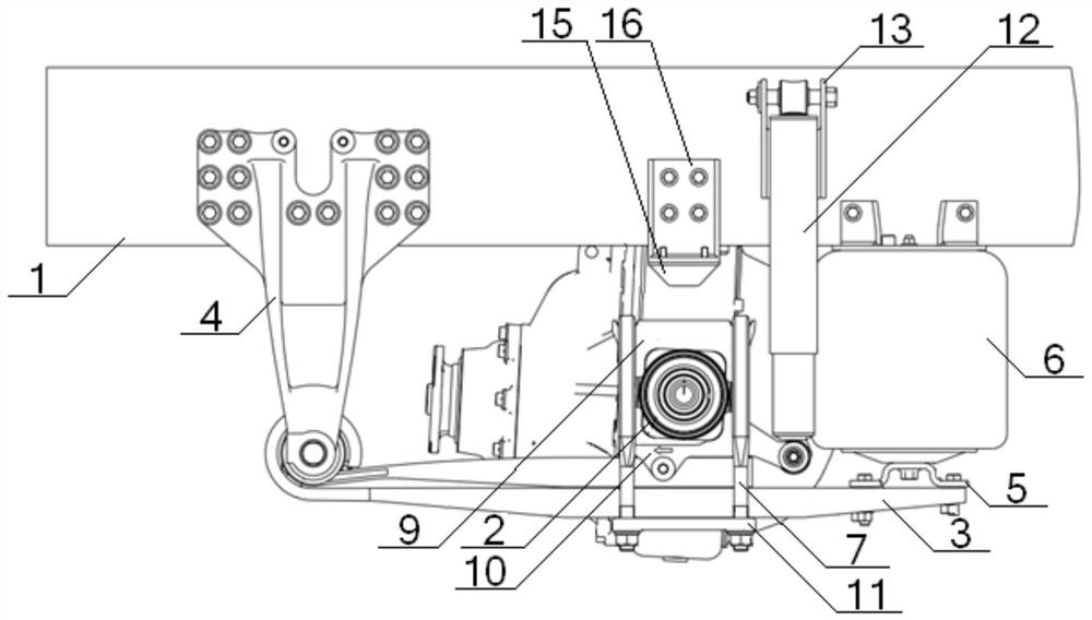
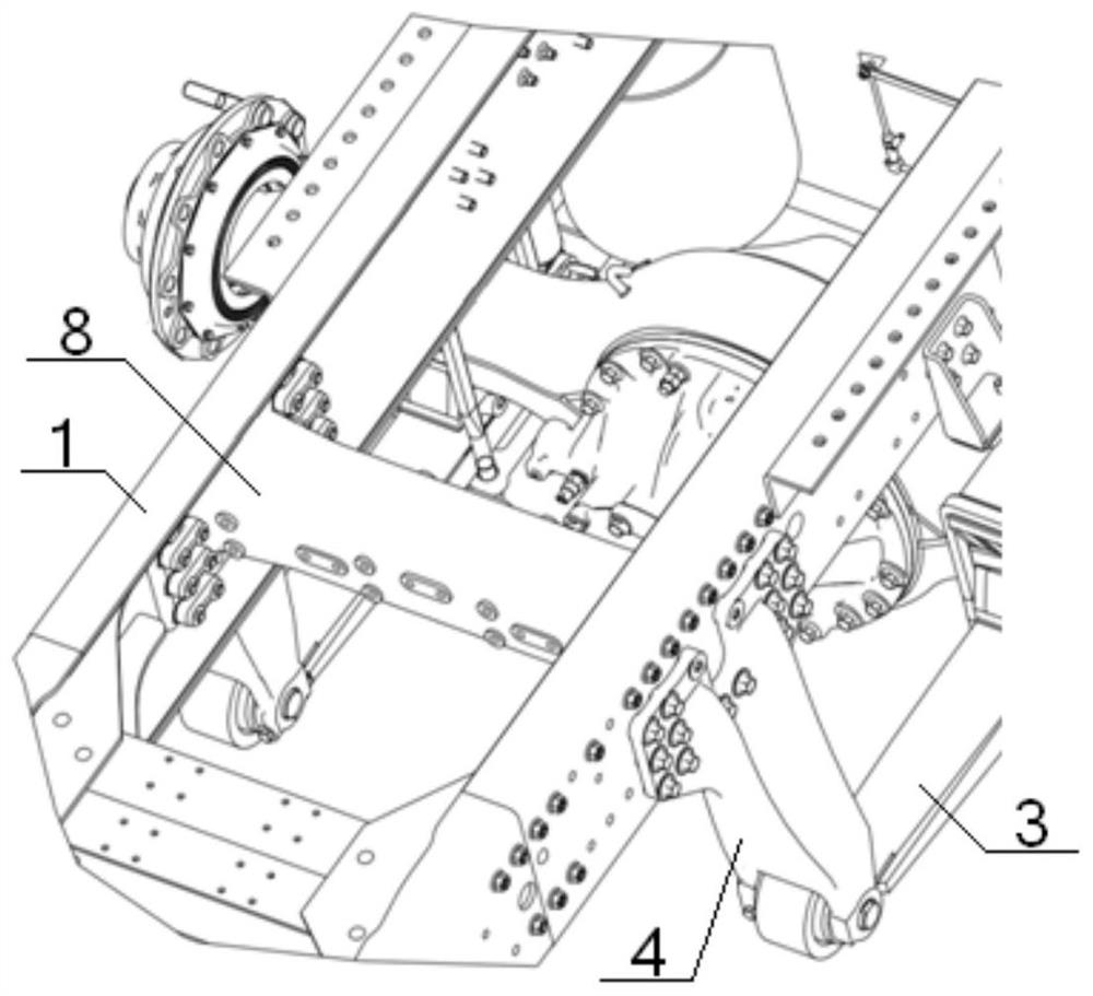
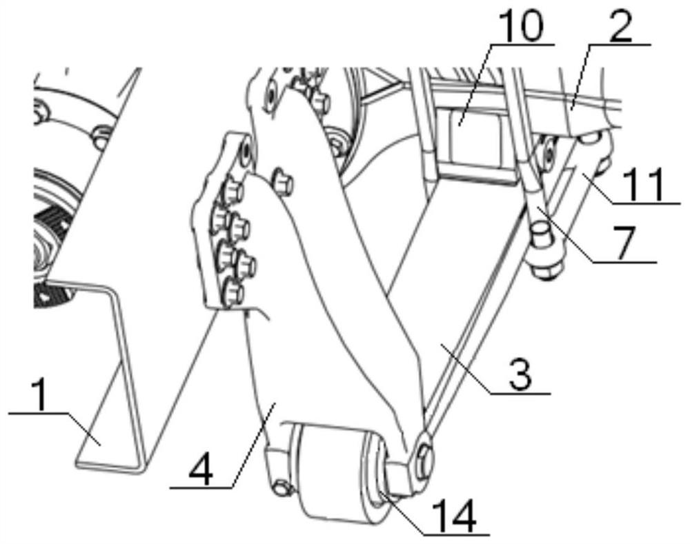
[0066] see Figure 1 to Figure 5 , a composite air suspension system that does not match the thrust rod, including a vehicle frame 1, an axle 2, and a guide arm 3, one end of the guide arm 3 is connected to the vehicle frame 1 through a guide arm bracket 4, and the guide arm 3 The other end of the air spring beam 5 is connected with one end of the air spring 6, the other end of the air spring 6 is connected with the vehicle frame 1, and the middle part of the guide arm 3 is connected with the axle 2 through the U-bolt 7; the composite The type air suspension system also includes a frame beam 8, the end of the frame beam 8 is connected with the guide arm bracket 4 through the vehicle frame 1, the guide arm 3 is located below the axle 2, and the guide arm 3 is provided with a The U-shaped bolt base plate 11, the lower cover plate 10 is arranged between the guide arm 3 and the axle 2, and the upper cover plate 9 is arranged above the axle 2, and the U-shaped bolt 7 spans the uppe...

Embodiment 2

[0068] Basic content is the same as embodiment 1, the difference is:

[0069] see Figure 1 to Figure 12 , the lower cover plate 10 comprises a base plate 101 and a No. 1 riser 102 and a No. 2 riser 103 symmetrically arranged on the upper end thereof, and the U-shaped groove formed by the base plate 101, the No. 1 riser 102 and the No. 2 riser 103 is used When the axle 2 is arranged, the middle part of the base plate 101 is provided with a No. 1 bolt hole 104 connected with the guide arm 3 , and a diagonal brace 105 is provided between the side of the No. 1 riser 102 away from the No. 2 riser 103 and the base plate 101 , the No. 2 vertical plate 103 is symmetrically provided with a No. 1 horizontal plate 106 and a No. 2 horizontal plate 107 away from the side of the No. 1 vertical plate 102, and the No. 1 horizontal plate 106 and the No. 2 horizontal plate 107 are all connected to the bottom plate 101, A reinforcing plate 108 is arranged between the No. 1 horizontal plate 106...

Embodiment 3

[0071] Basic content is the same as embodiment 1, the difference is:

[0072] see Figure 1 to Figure 8 , the guide arm bracket 4 includes a mounting plate 41 and a No. 1 support plate 42 and a No. 2 support plate 43 that are symmetrically arranged. One end is provided with a pair of No. 1 flanges 44, and one end of the No. 2 support plate 43 is connected with the mounting plate 41, and the other end of the No. 2 support plate 43 is provided with a pair of No. 2 flanges 45. The No. 1 support plate 42 No. 3 horizontal plate and No. 4 horizontal plate are sequentially arranged from top to bottom between No. 2 support plate 43, one end of No. 3 horizontal plate is connected with mounting plate 41, and the other end of No. 3 horizontal plate is connected with No. 5 vertical plate The middle part of the No. 4 horizontal plate is connected, and the No. 6 vertical plate connected with the end of the No. 4 horizontal plate is arranged between the No. 1 flange 44 and the No. 2 flange ...


PUM


Abstract

A combined type air suspension system without a thrust bar comprises a vehicle frame, a vehicle axle, a guide arm and a vehicle frame transverse beam. One end of the guide arm is connected with the vehicle frame through a guide arm support, and the other end of the guide arm is connected with an air spring through an air spring transverse beam. The end of the vehicle frame transverse beam is connected with the guide arm support through the vehicle frame. The guide arm is located below the vehicle axle. An upper cover plate and a lower cover plate are arranged on the upper side and the lower side of the vehicle axle. A U-shaped bolt strides over the upper cover plate, the lower cover plate and the guide arm in sequence and then is connected with a U-shaped bolt base plate. The lower cover plate is connected with a shock absorber, two lug plates are symmetrically arranged on the two side faces of the lower cover plate, and adjusting bolts are arranged on the lug plates and abut against the guide arm. A large gasket is arranged on the portion, connected with the guide arm support, of the guide arm. By the adoption of the design, the vehicle frame crack risk and the cost are reduced, the trafficability is improved, the steering performance is guaranteed, the tire abrasion is reduced, and the abrasion of the guide arm support can be avoided.

Description

technical field [0001] The invention relates to the technical field of automobile air suspension, in particular to a composite air suspension system that does not match a thrust rod, and is mainly suitable for reducing the risk and cost of vehicle frame cracking and improving vehicle trafficability. Background technique [0002] Compared with the leaf spring suspension, the air suspension can effectively improve the ride comfort of the vehicle, making the ride safer and more comfortable; when the load changes, it can automatically adjust to maintain the body height; the vehicle equipped with the air suspension has small vibration and can reduce the impact on The damage of electrical, instrumentation and other accessories of the body and chassis reduces the maintenance cost of the vehicle; reduces the impact on the road, protects the road surface, and reduces the maintenance cost of the highway, so it is more and more widely used in automobiles. [0003] Chinese patent, the a...

Claims


Application Information

Patent Timeline
Patent Type & Authority Patents(China)
IPC IPC(8): B60G11/46B60G13/00B62D21/02B62D21/11
CPCB60G11/46B60G13/005B60G2202/112B60G2202/152B60G2204/126B60G2204/129B62D21/02B62D21/11
Inventor 彭显威阳熹杜笑晨范培斌王江伟周生权邓杰辛梓田
Owner DONGFENG COMML VEHICLE CO LTD
Why Eureka
Try Eureka