
Embedded type bow ice breaking device based on resonance principle

An embedded and bow technology, applied in the field of machinery, can solve the problems of high structural strength requirements of the bow, high power requirements of icebreakers, and high wear rate of icebreakers, so as to avoid ice jamming, ensure the strength of gear teeth and Abrasion resistance, the effect of improving ice breaking ability

Active Publication Date: 2019-12-06
HARBIN ENG UNIV
View PDF9 Cites 1 Cited by
  • Summary
  • Abstract
  • Description
  • Claims
  • Application Information

AI Technical Summary

Problems solved by technology

The above three methods all have limitations in different aspects: the crushing method has high power requirements for the icebreaker, is only suitable for icebreaking operations on thinner ice layers, and is easy to be jammed by crushed ice; The strength requirements are high, and the impact of the strong vibration caused by the collision on the equipment and personnel on board cannot be ignored; the efficiency of the ballast method is low, the energy consumption is huge, and the large longitudinal tilt puts higher requirements on the normal operation of the equipment on board
Aiming at the above problems, a novel icebreaker bow and icebreaking method with the publication number CN104527919A utilizes the bow line shape inclined backwards, and an icebreaking blade is arranged above the bow, and the icebreaking blade exerts an icebreaking force on the thin ice layer, which can realize The thin ice layer is broken, but for the thick ice layer in the polar region, the ice-breaking blade wear rate of the invention is high, and the ice-breaking ability is poor

Method used


Image

  • Embedded type bow ice breaking device based on resonance principle
  • Embedded type bow ice breaking device based on resonance principle
  • Embedded type bow ice breaking device based on resonance principle

Examples


Embodiment Construction

[0016] The present invention will be further described below in conjunction with accompanying drawing:

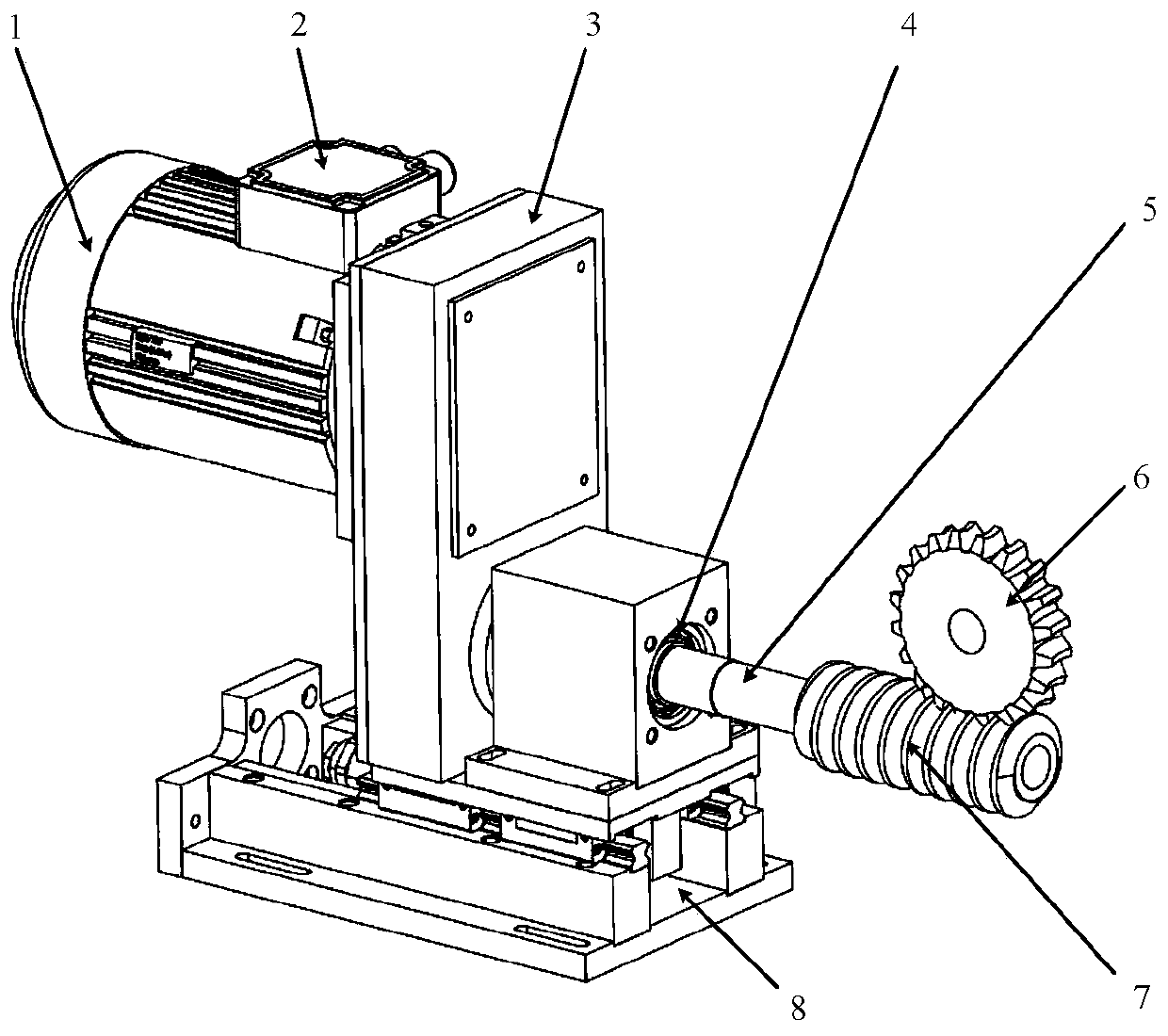
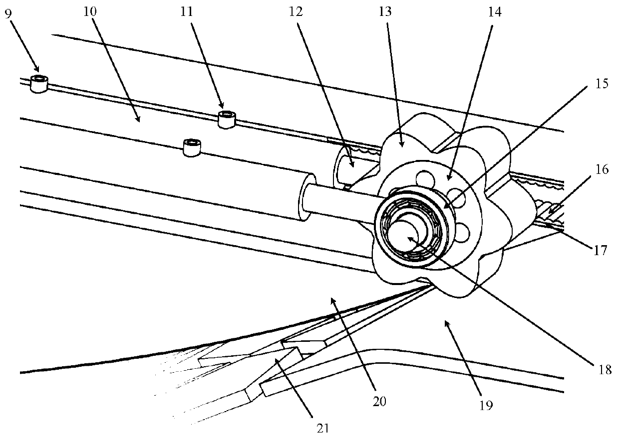
[0017] As shown in the figure, including the figure: 1. Motor; 2. Electric control box; 3. Reducer; 4. Bearing 1; 5. Transmission shaft 1; 6. Worm wheel; 7. Worm; 8. Reducer base; 9. Oil inlet; 10. Hydraulic cylinder; 11. Oil outlet; 12. Piston rod; 13. Ring gear; 14. Hub; 15. Bearing 2; 16. Buckle; 17. Leaf spring; 18. Transmission shaft 2; 19. Ice; 20. Bow; 21. Crushed ice

[0018] The invention relates to the field of mechanical technology, in particular to an embedded bow ice-breaking device based on the principle of resonance. The ice breaking device of the present invention includes a resonant wheel, a power system and a position scheduling system. The resonance wheel is mainly composed of a hub, a ring gear and a shaft, which is used to drive the bow structure to vibrate at a specific frequency after the icebreaker climbs onto the ice layer; The device structure i...


PUM


Abstract

The invention relates to the technical field of machines, and provides an embedded type bow ice breaking device based on a resonance principle. The device is mainly composed of a resonance wheel, a power system and a position dispatching system; the resonance wheel is mainly composed of a hub, a gear ring and a shaft and is used for driving a bow structure to vibrate at the specific frequency withan ice layer as a support when an ice breaking boat climbs to the ice layer; the power system is composed of a speed adjusting motor, a speed reducer and a worm and gear transmission device and usedfor proving power for the resonance wheel; the position dispatching system is composed of a pair of synchronous hydraulic cylinders, a buckle and a plate spring and used for adjusting the position ofthe resonance wheel and buffering impact loads of the ice layer to the resonance wheel; and the device has the obvious advantages that the device can effectively improve the ice breaking capacity under the condition that the water draining amount is not obviously increased, clamping by broken ice can be effectively avoided, wheel tooth strength and wear resistance can be ensured, and structure maneuverability can be improved.

Description

Technical field: [0001] The invention relates to the field of mechanical technology, in particular to an embedded bow ice-breaking device based on the principle of resonance. Background technique: [0002] With the rise of Arctic resource development, the rich oil, natural gas and other resources in the polar regions will play an inestimable role in supporting the future development of the world economy. In recent years, the melting of ice in the Arctic waters has made it possible to open the Arctic shipping lanes, so it poses higher challenges to the icebreaking capabilities of icebreakers and other aspects. The existing icebreakers are mainly divided into three categories according to the working principle: one is to crush the ice layer by the forward power of the icebreaker; The raised bow of the ship is driven onto the ice, and the ballast water is pumped to the front cabin, where the weight of the water crushes the ice. The above three methods all have limitations in ...

Claims


Application Information

Patent Timeline
IPC IPC(8): B63B35/08
CPCB63B35/083
Inventor 庞福振霍瑞东李海超彭德炜李玉慧单衍贺于晨张乾坤
Owner HARBIN ENG UNIV
Learn More