
Method for operating a textile machine and textile machine

A technology of textile machines and spinning machines, which is applied in spinning machines, open-end spinning machines, textiles and papermaking, etc., and can solve problems such as complicated processes and disadvantages

Active Publication Date: 2019-12-06
MASCHINENFABRIK RIETER AG
View PDF20 Cites 1 Cited by
  • Summary
  • Abstract
  • Description
  • Claims
  • Application Information

AI Technical Summary

Problems solved by technology

The current of the stepper motor must be cut off twice to position the wire guide at its zero position, which is a very complicated process
In addition, stepper motors do not apply torque when powered off, which is also a disadvantage

Method used


Image

  • Method for operating a textile machine and textile machine
  • Method for operating a textile machine and textile machine
  • Method for operating a textile machine and textile machine

Examples


Embodiment Construction

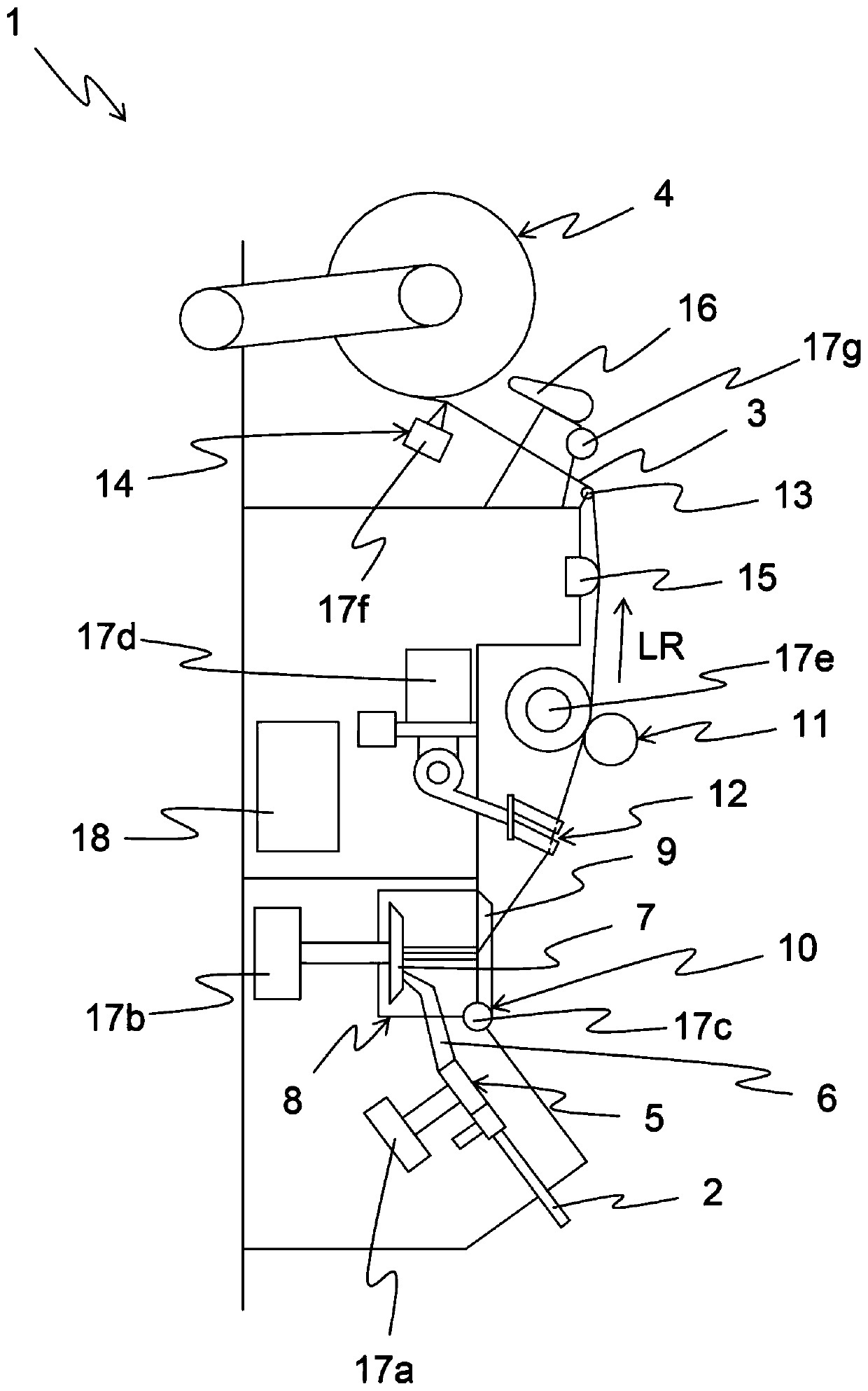
[0026] figure 1 A schematic side view of station 1 of the textile machine is shown. The textile machine may comprise a plurality of stations 1 in order to increase the productivity of the textile machine according to the number of the stations 1 . In the present embodiment, station 1 is configured as a spinning station of a rotor spinning machine. However, the invention is applicable in principle to any textile machine, in particular other open-end spinning machines, air-jet spinning machines or eg winders.

[0027] Station 1 produces yarn 3 from fiber strip 2 . The wire 3 passes through the station 1 in the feeding direction LR and is finally wound onto the reel 4 .

[0028] First, however, the fiber ribbon 2 is dispersed into its individual fibers 6 in the dispersing unit 5 . The individual fibers 6 are led to a spinning rotor 7 which produces the yarn 3 from the individual fibers 6 . In the present embodiment, the spinning rotor 7 is arranged in a spinning box 8 which ...


PUM


Abstract

The invention relates to a method of operating a textile machine, in particular a free end spinning machine or an air jet spinning machine, wherein the textile machine comprises a plurality of stations (1) driven at least partially by a single motor, wherein the stations (1) are associated with at least one stepping motor (17). According to the invention, the load variable, in particular the loadangle, of the stepping motor (17) is measured, and based on the change of the load variable, in particular the increase of the load angle, the elements driven by the stepping motor (17) are identified, (5, 7, 9, 11, 12, 14, 16) approaching the final position (E). The invention also relates to a textile machine, particularly a free end spinning machine or an air jet spinning machine, which comprises a plurality of stations (1) driven at least partially by a single motor, wherein the station (1) is associated with at least one stepping motor (17), and wherein each station (1) comprises means formeasuring a load variable of the stepping motor (17), in particular a load angle, and a controller (18) for operating the stepping motor (17) according to the foregoing operation.

Description

technical field [0001] The present invention relates to a method of operating a textile machine, in particular an open-end or air-jet spinning machine, wherein the textile machine comprises a plurality of stations driven at least partly by a single motor, wherein the stations are associated with at least one stepper associated with the motor. The invention also relates to a textile machine, in particular an open-end or air-jet spinning machine, comprising a plurality of stations driven at least partly by a single motor, wherein the stations are associated with at least one stepper motor. Background technique [0002] DE 10 2005 002 409 A1 has disclosed a method and an apparatus for producing a winding device for cross-winding drums in a textile machine and for determining the zero position by means of a thread guide traversed by a stepper motor. In this case, the thread guide is first moved in the direction of the zero position by the stepper motor and positioned at a low s...

Claims


Application Information

Patent Timeline
IPC IPC(8): B65H63/00B65H67/08B65H54/74
CPCB65H63/006B65H67/08B65H54/74B65H2701/31D01H3/26D01H1/20D01H4/42D01H13/14D01H13/32B65H63/00H02P8/24H02P8/38H02P8/36D01H1/115D01H4/02
Inventor M·马莱克罗宾·维茵
Owner MASCHINENFABRIK RIETER AG
Learn More