Ka-band miniaturized filter antenna based on SIW structure

A filter antenna and ka-band technology, which is applied in the field of microwave and millimeter wave communication, can solve the problems of large filter antenna size and difficult integration, and achieve the effect of improving antenna gain and avoiding loss

Active Publication Date: 2019-12-06
XIDIAN UNIV
View PDF11 Cites 20 Cited by
  • Summary
  • Abstract
  • Description
  • Claims
  • Application Information

AI Technical Summary

Problems solved by technology

[0005] The purpose of the present invention is to propose a Ka-band miniaturized filter antenna based on the SIW structure to solve the problem that the existing filter antenna is too large in size and difficult to integrate

Method used


Image

  • Ka-band miniaturized filter antenna based on SIW structure
  • Ka-band miniaturized filter antenna based on SIW structure
  • Ka-band miniaturized filter antenna based on SIW structure

Examples


Embodiment Construction

[0026] The present invention will be further described below in conjunction with the accompanying drawings and specific embodiments.

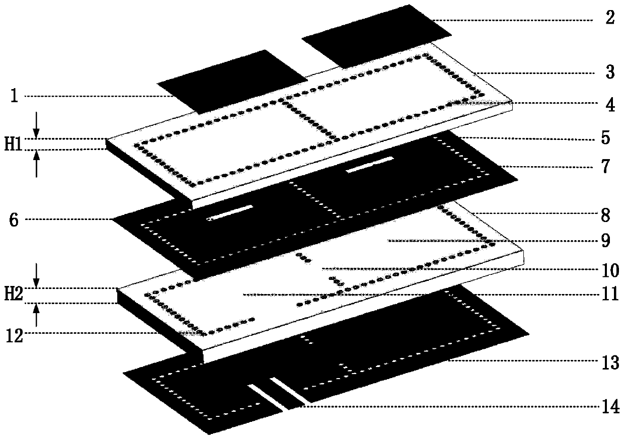
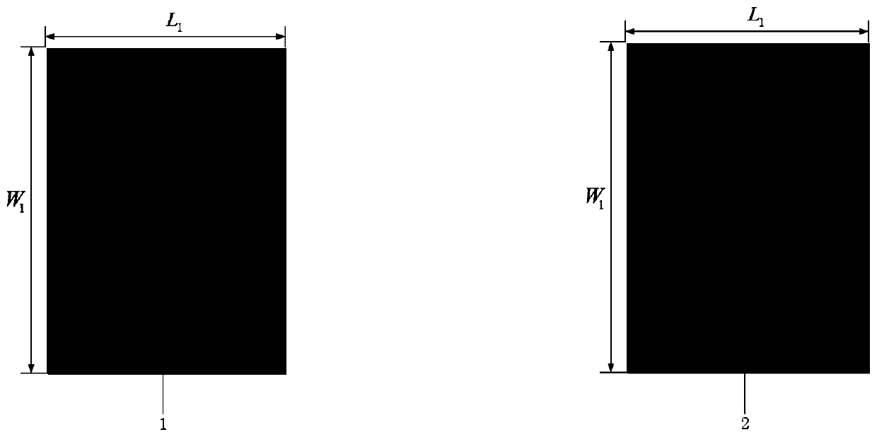
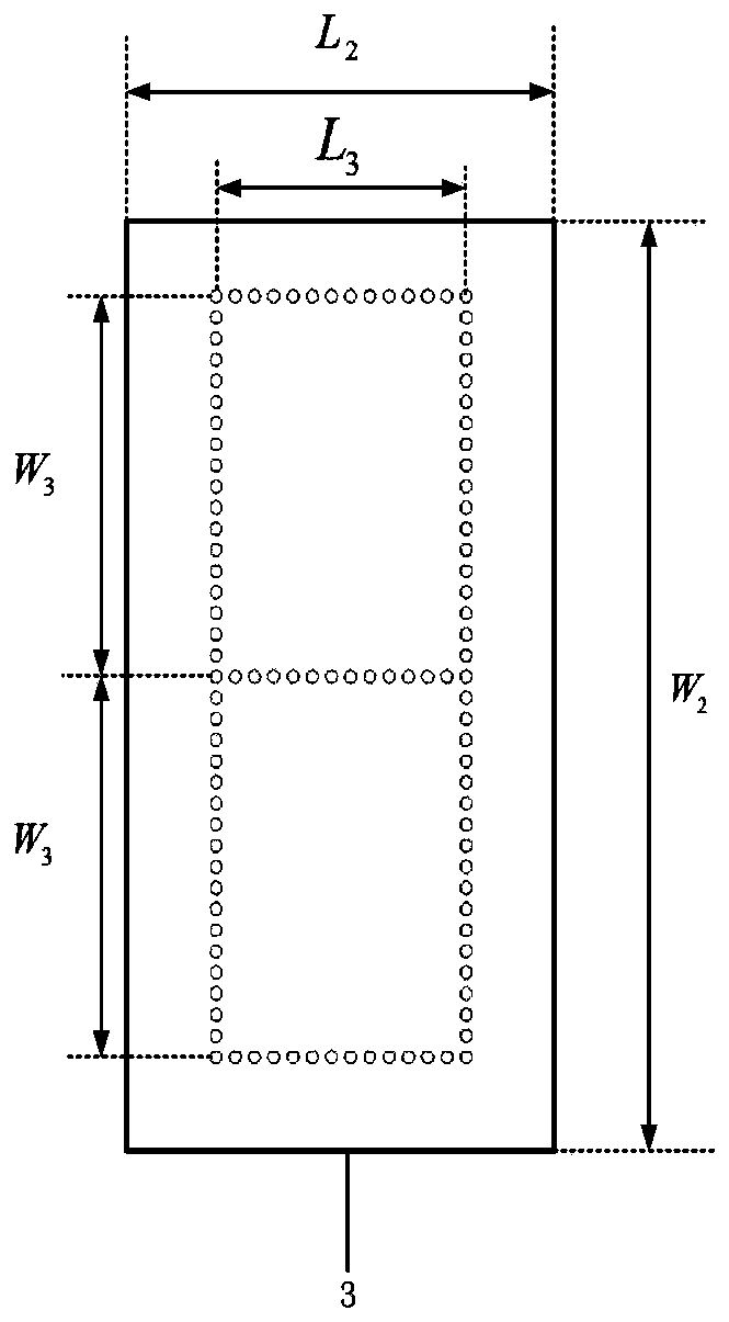
[0027] refer to figure 1 , this embodiment includes a first radiation unit 1, a second radiation unit 2, a second dielectric layer 3, a second metal layer 5, a first dielectric layer 8 and a first metal layer 13, wherein: the first metal layer 13 is provided with There is a coplanar waveguide 14; the first dielectric layer 8 is located between the first metal layer 13 and the second metal layer 5, and periodic metallized through holes 12 are arranged on the periphery and in the middle to form the first SIW resonant cavity 9 and the The second SIW resonant cavity 11, an inductive window 10 is opened between these two SIW resonant cavities; the second metal layer 5 is located on the first dielectric layer 8, and the first rectangular window 6 is opened on the left side, and the second rectangular window 6 is opened on the right side. Rectangular...


PUM


Abstract

The invention proposes a Ka-band miniaturized filter antenna based on a substrate integrated waveguide (SIW) structure to mainly solve the problem that a conventional filter antenna is too large in size and difficult to integrate. The Ka-band miniaturized filter antenna includes two metal layers, two dielectric layers and a microstrip radiation unit. A first metal layer (13) is provided with a coplanar waveguide (14). A first dielectric layer (8) is located between the first metal layer (13) and a second metal layer (5), and is provided with periodic metalized through holes (12) on its periphery and center to form two resonant cavities (9, 11). An inductive window (8) is arranged between the two resonant cavities for coupling the two resonant cavities. The second metal layer is provided with two rectangular windows (6, 7). A first radiation unit (1) is disposed on the upper left of the second dielectric layer (3), and a second radiation unit (2) is disposed on the upper right of the second dielectric layer (3). The two radiation units form a radiation array. The Ka-band miniaturized filter antenna has good frequency selectivity and high gain, is easy to integrate, and suitable forKa-band wireless communication.

Description

technical field [0001] The invention belongs to the technical field of microwave and millimeter wave communication, and in particular relates to a filter antenna which can be used for Ka-band wireless communication. Background technique [0002] In recent years, wireless communication technology has developed rapidly, and wireless communication systems tend to be miniaturized. As the key components in the wireless communication system, the filter and the antenna can be co-designed into a filter antenna to meet the requirement of miniaturization. At present, filter antennas that are easy to process and integrate have become a new research hotspot. [0003] Chinese patent CN202275943U discloses a horizontally polarized planar filter antenna. After the third-order SIW resonator, the filter antenna is realized by coupling the inductive window with a SIW slot radiation array. This patent adopts a horizontal structure as a whole, As a result, the plane size is too large, which i...

Claims


Application Information

Patent Timeline
Patent Type & Authority Applications(China)
IPC IPC(8): H01Q1/38H01Q15/00H01P1/208H01P1/203
CPCH01P1/203H01P1/208H01Q1/38H01Q15/0053
Inventor 董刚旷丁丁杨银堂
Owner XIDIAN UNIV
Why Eureka
Try Eureka