Nasal cavity implant and application thereof

A technology for implants and nasal cavity, which is applied in the field of medical devices to achieve good meshing ability, high-efficiency treatment effect, and stable release amount

Inactive Publication Date: 2019-12-10
PUYI (SHANGHAI) BIOTECHNOLOGY CO LTD
View PDF8 Cites 1 Cited by
  • Summary
  • Abstract
  • Description
  • Claims
  • Application Information

AI Technical Summary

Problems solved by technology

The active drug ingredients can be loaded on the drug carrier particles of 0.5-10 microns, and through the drug delivery device, such as dry powder inhaler, the drug powder particles can be effectively delivered to specific parts of the human body through the patient's

Method used


Image

  • Nasal cavity implant and application thereof
  • Nasal cavity implant and application thereof
  • Nasal cavity implant and application thereof

Examples


Embodiment 1

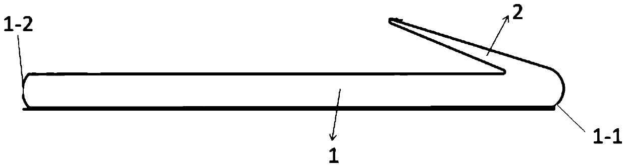
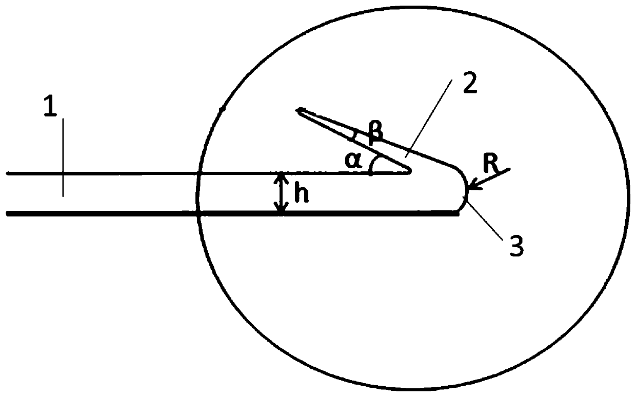
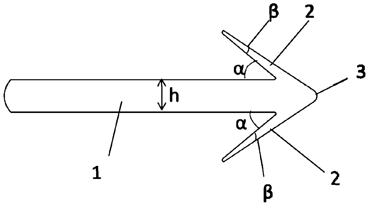
[0087] This embodiment provides an implant, consisting of figure 1 and figure 2It can be seen that the implant includes a main body 1 and an engaging part 2, the main body 1 includes a connecting end 1-1 and a free end 1-2, and the connecting end 1-1 and the engaging part 2 of the main body 1 are away from the surface of the main body 1. The rounded terminals 3 are connected continuously; the main body 1 is in the shape of a cylinder, and the diameter h of the cylinder is 0.5 mm; the shape of the engaging part 2 is conical, and the cone angle of the cone is β, and β is 30°; From the connecting end 1-1 to the free end 1-2 of the main body 1, the angle between the busbar of the engaging part 2 closest to the main body 1 and the outer wall of the main body 1 is α, and α is 50°; the contact surface of the engaging part 2 and the main body 1 The maximum linear distance between any two points of the cylinder is 80% of the diameter of the cylinder, which is 0.4mm; the radius R of t...

Embodiment 2

[0093] This embodiment provides an implant, the implant includes a main body and an engaging part, the main body includes a connecting end and a free end, and the surface of the engaging part away from the main body is continuously connected to the rounded terminal; wherein the shape of the main body is Cylinder, the diameter h of the cylinder is 0.8mm; the shape of the engaging part is conical, the cone angle of the cone is β, and β is 5°; towards the direction from the connecting end to the free end of the main body, the part of the engaging part closest to the main body The angle between the busbar and the outer wall of the main body is α, and α is 20°; the maximum linear distance between any two points on the contact surface of the engaging part and the main body is 50% of the diameter of the cylinder, which is 0.4mm; the connecting part and the main body The radius of the fillet is 50% of the diameter of the cylinder, which is 0.4mm; the number of engaging parts is 1.

[...

Embodiment 3

[0101] This embodiment provides an implant. The implant includes a main body and an engaging part. The main body includes a connection end and a free end. The surface of the engaging part away from the main body is continuously connected to the rounded terminal; wherein the shape of the main body is It is a cylinder, and the diameter h of the cylinder is 0.05mm; the shape of the engaging part is conical, and the cone angle of the cone is β, and β is 50°; towards the direction from the connecting end to the free end of the main body, the engaging part is closest to the main body The angle between the busbar and the outer wall of the main body is α, and α is 70°; the maximum linear distance between any two points on the contact surface of the engaging part and the main body is 100% of the diameter of the cylinder, which is 0.05mm; the engaging part is connected to the main body The radius of the fillet is 2% of the diameter of the cylinder, which is 0.001mm; the number of engagin...


PUM

PropertyMeasurementUnit
Diameteraaaaaaaaaa
Thicknessaaaaaaaaaa
Particle sizeaaaaaaaaaa

Abstract

The invention provides a nasal cavity implant and an application thereof. The nasal cavity implant comprises a main body which comprises a connecting end and a free end; and the connecting end comprises at least one meshing part and a fillet terminal. In a direction from the connecting end of the main body to the free end, an included angle between the surface, closest to the main body, of the meshing part and the outer wall surface of the main body is alpha, wherein the alpha is greater than or equal to 10 degrees and less than or equal to 90 degrees. When being implanted in the nasal cavitytissue, the nasal cavity implant has a relatively good capability of being meshed with the nasal cavity tissue on the premise of ensuring a relatively good slow-release effect (slow and stable releaseof drugs can be realized and an efficient treatment effect can be achieved with a relatively small dose), so that the nasal cavity implant can be prevented from being discharged out of the body together due to sneezing or rhinorrhea.

Description

technical field [0001] The invention belongs to the field of medical equipment, and relates to a nasal cavity implant and its application. Background technique [0002] The main clinical manifestation of allergic rhinitis is sneezing, with paroxysmal attacks several times a day, each time more than 3. There are foreign articles reporting that the general airflow velocity of a sneeze is 150 km / h, which is 41.7 m / s. The foam is sprayed three or four meters away, which is almost close to the central wind force of a 15-level typhoon. The general way of administration is nasal cavity or nasal passage administration, but this way of administration will be excreted together when sneezing or runny nose, so no good therapeutic effect can be achieved. [0003] CN101574507B discloses a nasal drug delivery system for treating headaches, including a nasal inhaler and a pharmaceutical composition, the nasal inhaler includes an elastic support and a drug-loading member arranged at the end...

Claims


Application Information

Patent Timeline
IPC IPC(8): A61M31/00
CPCA61M31/002A61M2207/00A61M2210/0618A61M2210/005
Inventor 夏佩佩晏伟魏征
Owner PUYI (SHANGHAI) BIOTECHNOLOGY CO LTD
Why Eureka
Try Eureka