Pushing type centrifugal machine

A centrifuge and pusher-type technology, applied in the field of centrifuges, can solve the problems of inability to separate the pusher centrifuge, unable to meet customer requirements, poor material dehydration effect, etc., to achieve better dehydration effect, better dehydration effect, design clever effect

Pending Publication Date: 2019-12-10
XIANGTAN HUIBO CENTRIFUGE
View PDF1 Cites 2 Cited by
  • Summary
  • Abstract
  • Description
  • Claims
  • Application Information

AI Technical Summary

Problems solved by technology

[0004] In the prior art, the material of the pusher centrifuge has a narrow range of adaptation. When the material process changes or the feed concentration is too low, it will not be possible to use the pusher centrifuge to separate; Most of the drum device designs are simple in structure, and the material dehydration effect is not good enough to meet customer requirements; therefore, it is urgent to develop a pusher type centrifuge to solve the above problems

Method used


Image

  • Pushing type centrifugal machine
  • Pushing type centrifugal machine
  • Pushing type centrifugal machine

Examples


Embodiment Construction

[0035] In order to enable those skilled in the art to better understand the technical solution of the present invention, the present invention will be described in detail below in conjunction with the accompanying drawings. The description in this part is only exemplary and explanatory, and should not have any limiting effect on the protection scope of the present invention. .

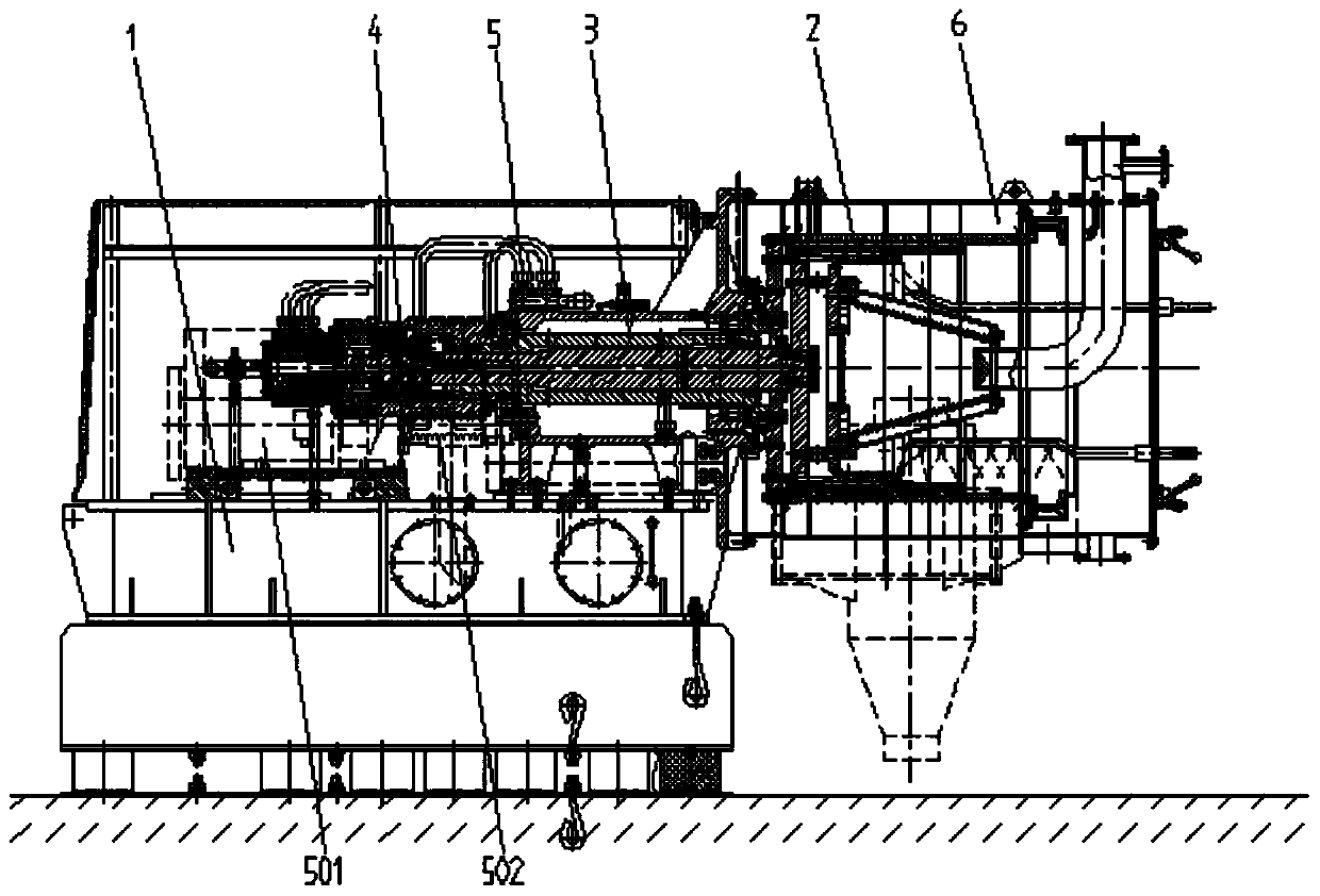
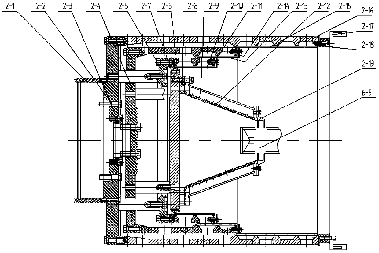
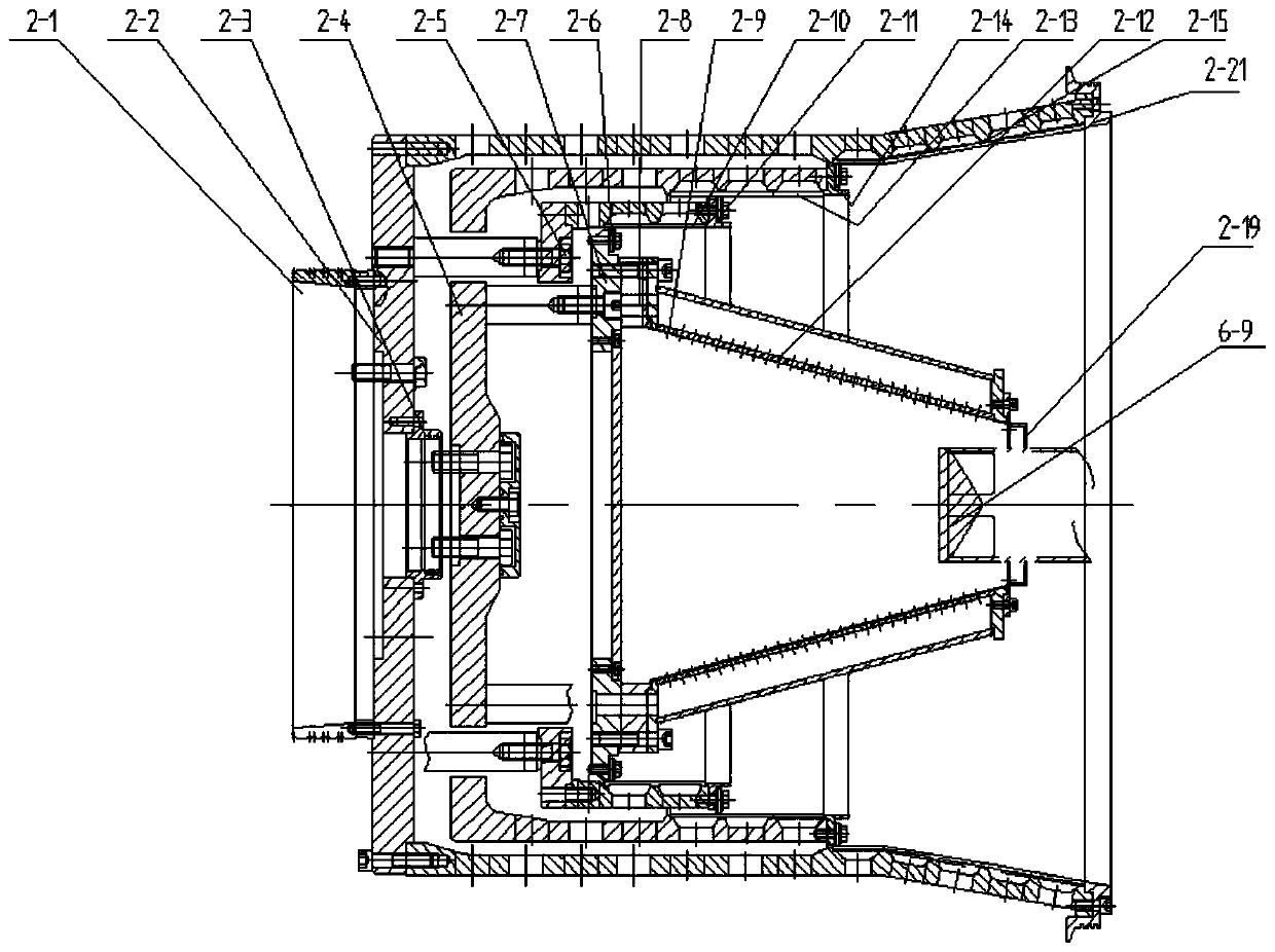
[0036] Such as Figure 1-Figure 8 As shown, the specific structure of the present invention is as follows: it includes a machine base 1, on which a driving device 100 is arranged, and the driving device 100 is connected with the first group of shafts and bearing assemblies 3 through the composite oil cylinder assembly 4 or the transmission device 8, and the second One end of a set of shaft and bearing assemblies 3 is movably provided with a drum assembly 2, and the outer periphery of the drum assembly 2 is provided with a casing assembly 6; the drum assembly 2 includes a water retaining ring 2 connecte...


PUM


Abstract

The invention discloses a pushing type centrifugal machine which comprises a machine base, a drive device, a composite cylinder assembly, a shaft and bearing assembly, a rotary drum assembly and a housing assembly; the rotary drum assembly comprises a water stop ring and a third-stage rotary drum, a second-stage rotary drum is arranged at the inner circumference of the third-stage rotary drum, a first-stage rotary drum is arranged at the inner circumference of the second-stage rotary drum, a pushing disc is arranged at the inner circumference of the first-stage rotary drum, a distributing opening is formed in the circumference of the side end of the pushing disc, a centrifugal distributor is arranged at the circumference of the side end of the distributing opening, a centrifugal mesh pressing ring is arranged at one end of the centrifugal distributor, and a feeding pipe alternately penetrates through the centrifugal mesh pressing ring; a first-stage screen cloth is arranged on the first-stage rotary drum, a second-stage screen cloth is arranged on the second-stage rotary drum, and a third-stage screen cloth is arranged on the third-stage rotary drum; a first-stage pushing piece, asecond-stage pushing piece and a third-stage pushing piece are arranged on the pushing disc, the first-stage rotary drum and the second-stage rotary drum respectively. The pushing type centrifugal machine is convenient to use and maintain, due to the unique design of the rotary drum device, the material dehydration effect is good, the pushing type centrifugal machine is applicable to a low-concentration suspension, and the service life is long.

Description

technical field [0001] The invention relates to a centrifuge, in particular to a pusher type centrifuge. Background technique [0002] The centrifuge is used centrifugal force , separate liquid with solid particles or liquid and liquid The mechanics of the components in the mixture. Centrifuges are mainly used to suspension Separate the solid particles in the liquid from the liquid, or separate the two in the emulsion density Separate different, immiscible liquids (such as separating cream from milk); it can also be used to remove liquid from wet solids, such as drying wet clothes with a washing machine; special ultra-speed tube separators can also separate different Density gas mixture; using the characteristics of different sedimentation speeds of solid particles of different densities or particle sizes in liquids, some decanter centrifuges can also classify solid particles according to density or particle size. [0003] A pusher centrifuge is a continuously ...

Claims


Application Information

Patent Timeline
Patent Type & Authority Applications(China)
IPC IPC(8): B04B1/00B04B7/08B04B7/16B04B11/08B04B15/06B04B9/02B04B11/02
CPCB04B1/00B04B7/08B04B7/16B04B9/02B04B11/02B04B11/08B04B15/06
Inventor 王细枧王深波颜国良
Owner XIANGTAN HUIBO CENTRIFUGE
Why Eureka
Try Eureka