Displacement measurement system and photoetching machine

A technology for displacement measurement and beam measurement, which is applied in the field of displacement measurement systems and lithography machines, can solve problems such as inaccurate measurement beam compensation, poor measurement accuracy and stability, and sensor changes, so as to reduce the measurement optical path, improve measurement accuracy and Stability, the effect of shortening the measurement light path

Active Publication Date: 2019-12-10
SHANGHAI MICRO ELECTRONICS EQUIP (GRP) CO LTD
View PDF8 Cites 0 Cited by
  • Summary
  • Abstract
  • Description
  • Claims
  • Application Information

AI Technical Summary

Problems solved by technology

[0005] In the current technology, in order to improve the problem of poor measurement accuracy and stability of the laser interferometer affected by the environment, it is mainly by improving the stability of the environment during the laser interferometer measurement beam propagation process, or by measuring the measurement beam propagation process. The actual value of the refractive index of air compensates the wavelength of the measurement beam in real time to improve the measurement accuracy and stability of the laser interferometer
Compensate the wavelength of the measurement beam. In this way, more sensors need to be installed to measure the temperature and pressure of the envi

Method used


Image

  • Displacement measurement system and photoetching machine
  • Displacement measurement system and photoetching machine
  • Displacement measurement system and photoetching machine

Examples


Embodiment 1

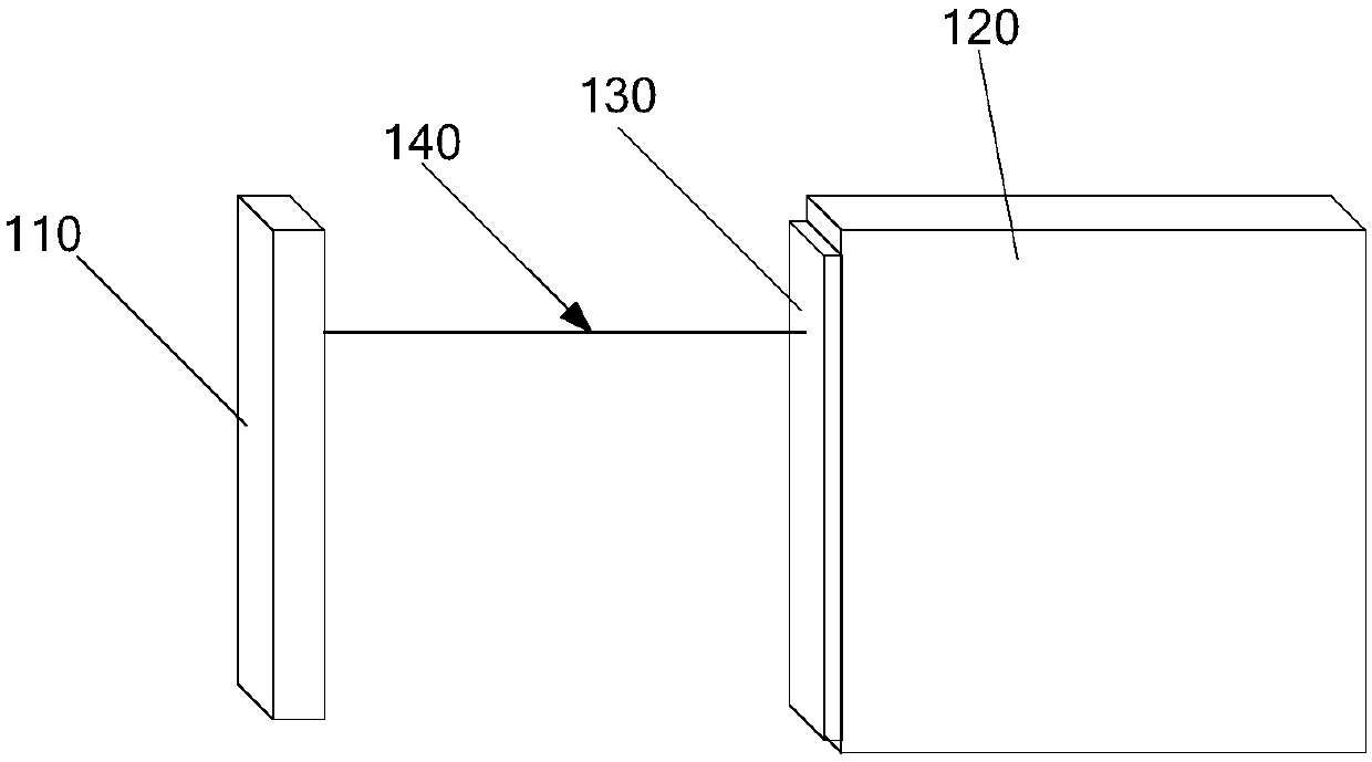
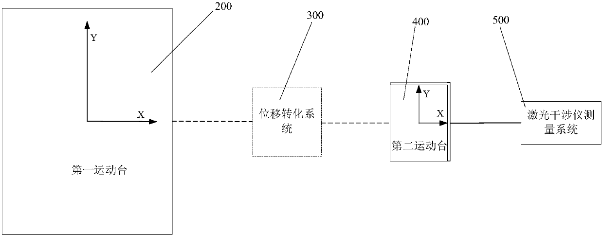
[0048] This embodiment provides a displacement measurement system. refer to figure 2 , figure 2 is a schematic diagram of a displacement measurement system in Embodiment 1 of the present invention, the displacement measurement system is used to measure the displacement information of the first moving platform 200, and the displacement measurement system includes a displacement conversion device 300, a second moving platform 400, Laser interferometer measuring device 500 and control device ( figure 2 not shown).

[0049] In this embodiment, the displacement measurement system is described by taking the movement of the first moving platform 200 along the X-axis direction as an example.

[0050] In this embodiment, the first moving stage 200 , the second moving stage 400 and the laser interferometer measuring device 500 are sequentially distributed along the X-axis direction.

[0051] Such as figure 2 As shown, the second moving table 400 moves along the X-axis direction...

Embodiment 2

[0058] This embodiment provides a displacement measurement system, and it can be understood that the displacement measurement system in this embodiment is a specific implementation manner of the displacement measurement system in Embodiment 1.

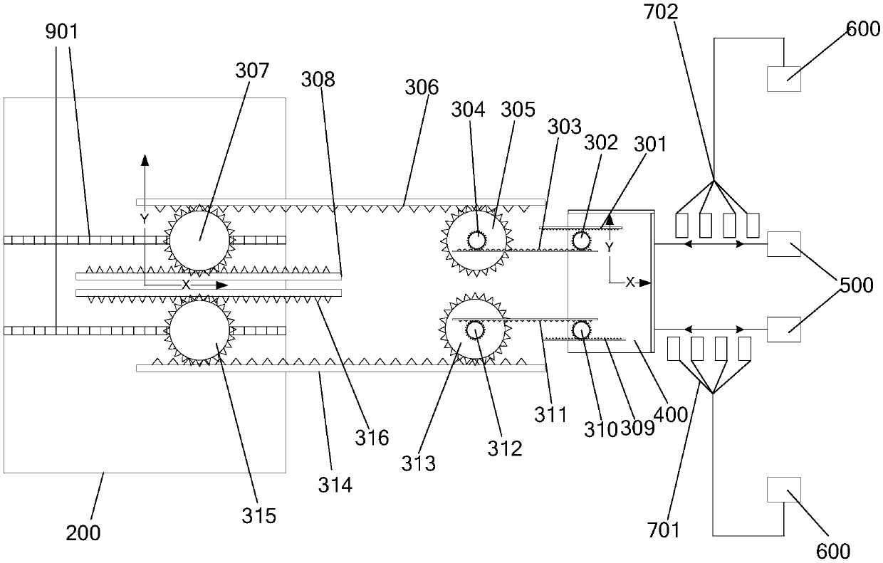
[0059] image 3 is a schematic structural diagram of the displacement measurement system in Embodiment 2 of the present invention, refer to image 3 , the displacement conversion device 300 is a gear train. The input end of the gear train is connected with the second motion table 400, the output end of the gear train is connected with the first motion table 200, and the gear train is used to move the second motion table 400 along the X The movement of the axis is converted into the displacement of the second moving platform 400 amplified according to a predetermined ratio and drives the first moving platform 200 to move.

[0060] Such as image 3 Said, the gear train includes a first gear train and a second gear train.

[0061] The...

Embodiment 3

[0087] This embodiment provides a displacement measurement system, and it can be understood that the displacement measurement system in this embodiment is a specific implementation manner of the displacement measurement system in Embodiment 1.

[0088] Figure 4 is a schematic structural diagram of the displacement measurement system in Embodiment 3 of the present invention, refer to Figure 4 , the displacement conversion device 300 includes: a displacement detector, a signal amplifier 331 and a linear drive device 341 .

[0089] The displacement detector is used to detect the displacement information of the second moving table 400 along the X-axis direction.

[0090] Specifically, the displacement detector includes a sliding piece 321 , a sliding rail 322 and an electrical signal measuring member 323 . The sliding piece 321 is fixedly connected with the second moving platform 400 . The slide rail 322 is fixedly arranged. The slide piece 321 cooperates with the slide rail...


PUM


Abstract

The invention provides a displacement measurement system, which is used for measuring the displacement information of a first motion platform moving along a predetermined direction, and comprises a second motion platform moving parallel to the predetermined direction; a laser interferometer measuring device which is used for measuring the displacement information of the second moving table movingalong a preset direction; a displacement conversion device which is used for amplifying the movement of the second moving table along the preset direction according to a preset proportion and drivingthe first moving table to move along the preset direction; a control device which is used for amplifying the displacement information of the second moving table moving along the preset direction intothe displacement information of the first moving table moving along the preset direction according to a preset proportion, wherein the first moving table, the second moving table and the laser interferometer measuring device are sequentially distributed along the preset direction. According to the displacement measurement system and the photoetching machine, the measurement precision and stabilityof the displacement measurement system can be improved.

Description

technical field [0001] The invention relates to the technical field of position measurement, in particular to a displacement measurement system and a photolithography machine. Background technique [0002] Laser interferometry linear displacement technology is a standard measurement technology with high precision, which is widely used in precision and ultra-precision machining, microelectronic equipment, nanotechnology industrial equipment and national defense equipment and other fields. figure 1 is a schematic diagram of a displacement measurement system such as figure 1 As shown, the displacement measurement system is used to measure the displacement information of the moving platform, and the displacement measurement system includes a laser interferometer 110 . The moving table 120 is provided with a reflector 130 capable of reflecting the measurement beam 140 emitted by the laser interferometer 110 . The measuring beam 140 of the laser interferometer 110 is reflected f...

Claims


Application Information

Patent Timeline
IPC IPC(8): G01B11/02G03F7/20
CPCG01B11/02G03F7/7085
Inventor 张静静
Owner SHANGHAI MICRO ELECTRONICS EQUIP (GRP) CO LTD
Why Eureka
Try Eureka