
A two-degree-of-freedom homodyne grating interferometer displacement measurement system

A technology of grating interference and displacement measurement, which is applied in the direction of measuring devices, instruments, and optical devices, can solve problems such as the inability to eliminate the influence of DC components and amplitude changes, limit the measurement efficiency and accuracy, and limit the measurement accuracy of the workpiece table. The effect of light weight, convenient application and simple structure

Active Publication Date: 2016-09-28
TSINGHUA UNIV +1
View PDF12 Cites 0 Cited by
  • Summary
  • Abstract
  • Description
  • Claims
  • Application Information

AI Technical Summary

Problems solved by technology

Netherlands ASML company US patent US7,102,729B2 (disclosure date August 4, 2005), US7,483,120B2 (disclosure date November 15, 2007), US7,,940,392B2 (disclosure date December 24, 2009) , Publication No. US2010 / 0321665A1 (publication date: December 23, 2010) discloses a planar grating measurement system and layout scheme applied to ultra-precision workpiece tables of lithography machines. The measurement system mainly uses a one-dimensional or two-dimensional plane The grating cooperates with the reading head to measure the horizontal large-stroke displacement of the workpiece table, and height sensors such as eddy currents or interferometers are used to measure the displacement in the height direction, but the application of various sensors limits the measurement accuracy of the workpiece table
U.S. patent document US7,864,336B2 (published on January 4, 2011) discloses a grating interferometer measurement system applied to an ultra-precision workpiece stage of a lithography machine. The system utilizes the Littrow conditional grating reflection of two reading heads to realize Displacement measurement, but requires many components and large volume, and the measurement efficiency and accuracy are limited due to the calculation through the results of two reading heads
U.S. Patent Publication No. US2011 / 0255096A1 (published on October 20, 2011) of ZYGO Corporation of the United States discloses a grating measurement system applied to ultra-precision workpiece tables of lithography machines. The measurement system also uses one-dimensional or two-dimensional gratings to cooperate with A specific reading head realizes displacement measurement, which can simultaneously measure horizontal and vertical displacements, but the structure is complex; Japanese CANON company US Patent Publication No. US2011 / 0096334A1 (publication date April 28, 2011) discloses a heterodyne interferometry In this interferometer, a grating is used as the objective mirror, but the interferometer can only realize one-dimensional measurement
In the research paper "Design and construction of a two-degree-of-freedom linear encoder for nanometric measurement of stage position and straightness. Precision Engineering 34 (2010) 145-155", Japanese scholar GAOWEI proposed a method using the principle of diffraction interference Single-frequency two-dimensional grating measurement system, which can realize horizontal and vertical displacement measurement at the same time, but due to the use of single-frequency laser, the measurement signal is susceptible to interference and the accuracy is difficult to guarantee
In addition, Chinese Patent Literature Publication No. CN103307986A (disclosure date: September 18, 2013) and CN103322927A (disclosure date: September 18, 2013) respectively disclose a heterodyne grating interferometer measurement system. The structure of the reading head adopts the optical two subdivision optical path design, which leads to the problem of low resolution, and adopts the principle of heterodyne phase detection, which cannot eliminate the influence of DC component and amplitude change.

Method used


Image

  • A two-degree-of-freedom homodyne grating interferometer displacement measurement system
  • A two-degree-of-freedom homodyne grating interferometer displacement measurement system
  • A two-degree-of-freedom homodyne grating interferometer displacement measurement system

Examples


Embodiment Construction

[0015] The structure, principle and specific implementation of the present invention will be further described in detail below in conjunction with the accompanying drawings.

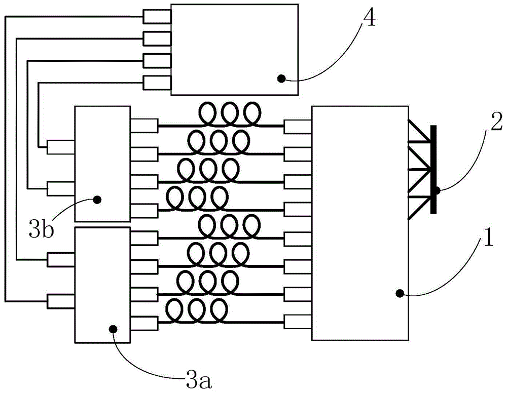
[0016] Please refer to figure 1 , figure 1 It is a schematic diagram of the displacement measurement system of the first homodyne grating interferometer of the present invention. Such as figure 1 As shown, the two-degree-of-freedom homodyne grating interferometer displacement measurement system includes a grating interferometer 1, a measurement grating 2, a first preprocessing unit 3a, a second preprocessing unit 3b, and a signal processing unit 4, and the measurement grating 2 is a one-dimensional Reflective grating.

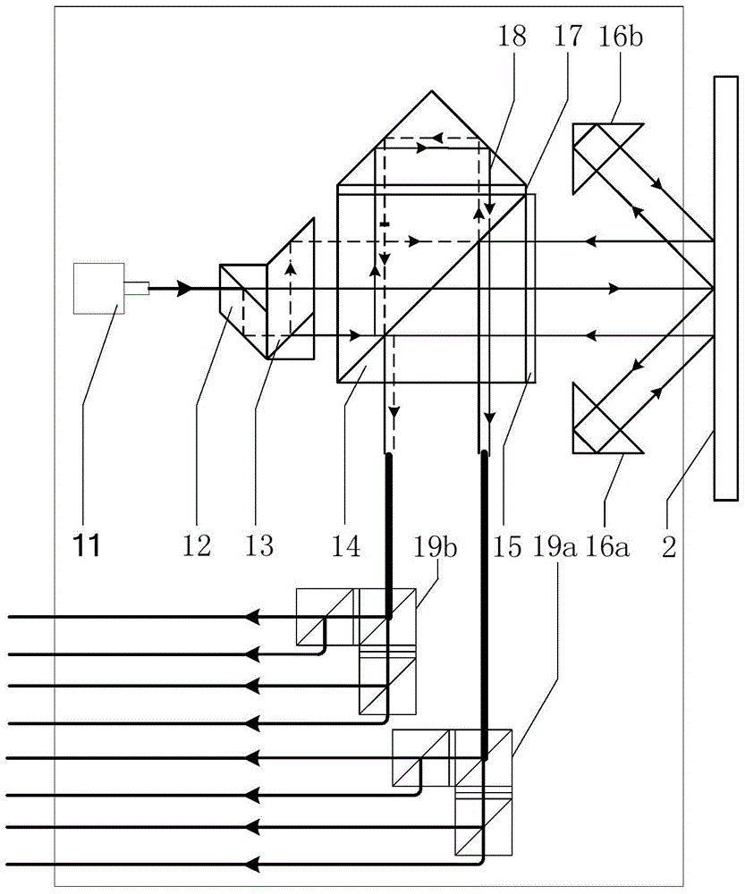
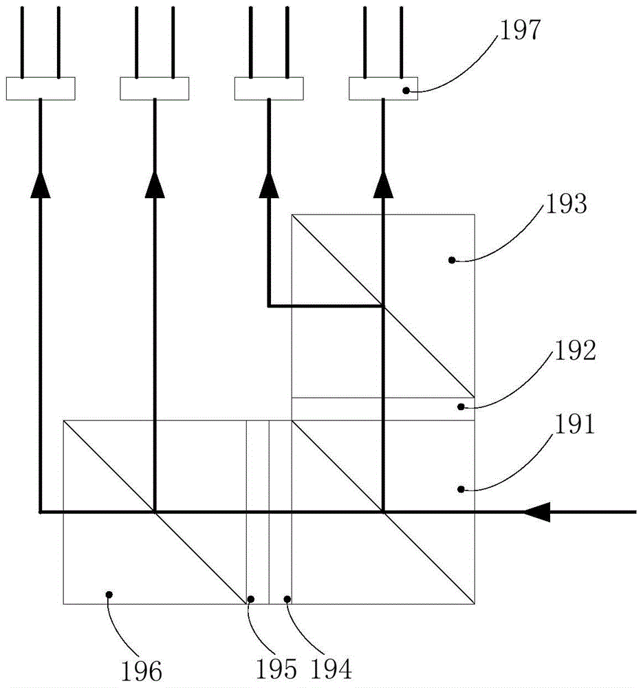
[0017] Please refer to figure 2 , figure 2 It is a schematic diagram of the internal structure of the first grating interferometer of the present invention. The grating interferometer 1 includes a laser tube 11, a first lateral displacement beamsplitter prism 12, a second lateral di...


PUM


Abstract

A two-degree-of-freedom homodyne grating interferometer displacement measurement system comprises a grating interferometer, a measuring grating, a preprocessing unit and a signal processing unit. The grating interferometer comprises a laser tube, a lateral displacement beam splitter prism, a polarization beam splitter prism, a quarter wave plate, a referencing grating, a refraction component and a four-channel homodyne structure. The system achieves displacement measurement based on grating diffraction, optical Doppler and homodyne signal processing. The grating interferometer outputs optical signals to the preprocessing unit, and the optical signals are converted into electric signals and transmitted to the signal processing unit. When the grating interferometer and the measuring grating do two-degree-of-freedom linear relative motion, the system can output two pieces of linear displacement. According to the two-degree-of-freedom homodyne grating interferometer displacement measurement system, a secondary diffraction principle is adopted to achieve four optical subdivisions, the sub-nanometer and even higher resolution ratio can be achieved, and the two pieces of the linear displacement can be measured. Homodyne signal processing is adopted, the influences brought by the DC component change and the amplitude change can be eliminated, and the two-degree-of-freedom homodyne grating interferometer displacement measurement system has the advantages of being insensitive to environment, high in measurement precision and the like.

Description

technical field [0001] The invention relates to a grating measurement system, in particular to a two-degree-of-freedom homodyne grating interferometer measurement system. Background technique [0002] In nanometer precision positioning and displacement monitoring, laser interferometry is the most widely used non-contact precision measurement technology. Heterodyne and homodyne laser interferometry are usually used. Heterodyne interferometry has the advantages of fast response, large measurement range, and strong anti-interference ability. However, due to the influence of factors such as light source, optical device adjustment error, processing error, and environment in the interferometer, the orthogonally polarized measurement light and reference light cannot be completely separated, resulting in the existence of nonlinear errors, even exceeding 10nm in large cases. And with the continuous improvement of motion indicators such as measurement accuracy, measurement distance, ...

Claims


Application Information

Patent Timeline
Patent Type & Authority Patents(China)
IPC IPC(8): G01B11/02
Inventor 刘召朱煜张鸣吴亚风王磊杰成荣穆海华胡金春徐登峰尹文生胡楚雄杨开明祁利山
Owner TSINGHUA UNIV
Learn More