Micro-strip filter composed of C-shaped resonance pairs

A technology of microstrip filters and resonators, applied in waveguide devices, electrical components, circuits, etc., can solve the problems of increasing design synthesis difficulty and structure realization difficulty, large and complex filter size, etc., and achieves easy design and small size Dimensional, topologically simple effects

Active Publication Date: 2019-12-10
SOUTHWEST CHINA RES INST OF ELECTRONICS EQUIP
View PDF5 Cites 3 Cited by
  • Summary
  • Abstract
  • Description
  • Claims
  • Application Information

AI Technical Summary

Problems solved by technology

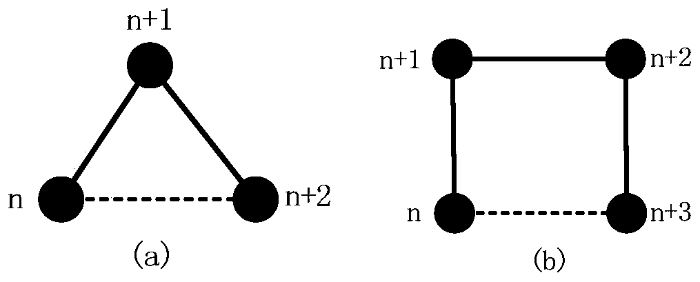
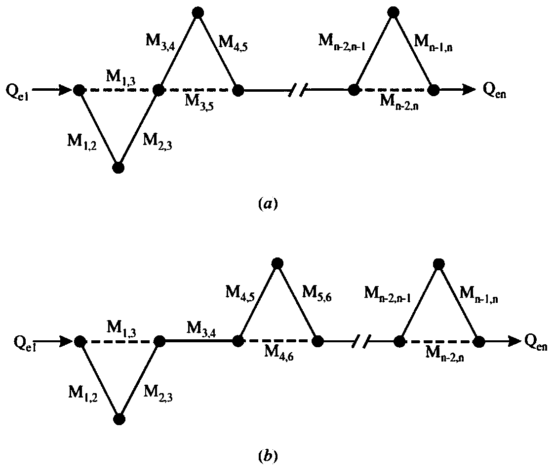
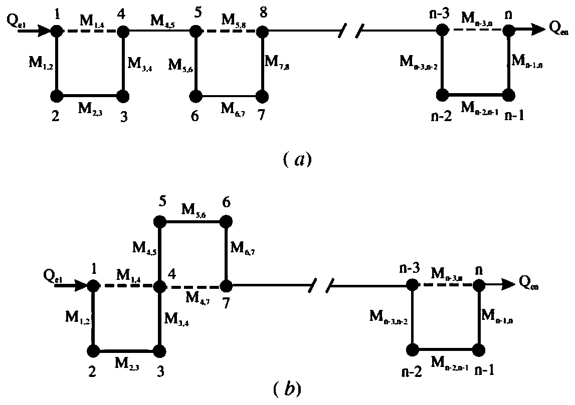
Although this method is extremely flexible for improving the out-of-band rejection of the filter, the disadvantage is that it often requires the use of complex topological structures, the resonators are usually not arranged in a straight line, and cross-coupling needs to be introduced between non-adjacent resonators, which increases the difficulty of design synthesis and structural implementation difficulty, the size of the filter in the horizontal plane is relatively large

Method used


Image

  • Micro-strip filter composed of C-shaped resonance pairs
  • Micro-strip filter composed of C-shaped resonance pairs
  • Micro-strip filter composed of C-shaped resonance pairs

Examples


Embodiment 1

[0039] Such as Image 6 As shown, a microstrip filter composed of C-shaped resonant pairs, including: N C-shaped resonant pairs, where the value of N is 3, and the three C-shaped resonators are CRP 1, CRP 2, and CRP 3, respectively. The formed filter is a 6-order filter; the three C-shaped resonant pairs are arranged in a straight line according to the linear topology to form a C-shaped resonant pair queue; the C-shaped resonant pair queue is provided with an input resonator and an output resonant The input resonator and the output resonator are respectively connected with high impedance lines, the high impedance line at the input end is connected with the input feeder line to realize the input coupling of the filter, and the high impedance line at the output end is connected with the output feeder line to realize The output coupling of the filter, the two together realize the external coupling of the filter.

[0040] Preferably, CRP 1 includes two oppositely placed C-shaped ...

Embodiment 2

[0048] Image 6 In the 6th-order C-band filter, the X-band microstrip filter can be obtained by adjusting the resonant frequency of the resonant pair and the coupling coefficient between the resonant pair, and its frequency response is as follows Figure 10 Shown in thin line. If you want to get a response curve with higher near-end suppression and better square coefficient, you can add CRP on this basis to form a higher-order filter. Therefore, in this filter, you can increase the number of C-shaped resonant pairs , to further improve the out-of-band suppression.

[0049] Therefore, on the basis of Example 1, as Figure 9 As shown, two CRPs are added to the 6th-order filter to form a 10th-order filter with the same frequency band. Its response curve see Figure 10 . Comparing the response curves of the 6th-order and 10th-order filters, it can be seen that after the number of CRPs increases to 5, the transmission zeros on the left and right sides of the passband are close...

Embodiment 3

[0051] The number N of CRPs is selected as 3, that is, the filter order is 6, and the structure of the 6th-order Ka-band filter on the ceramic substrate is as follows: Figure 12 shown. Its electrical performance curve is as Figure 14 As shown by the light-medium curve, there are transmission zeros at both ends of the passband that improve out-of-band rejection, while the circuit maintains a simple topology.


PUM


Abstract

The invention relates to the field of microwave circuits, and discloses a micro-strip filter composed of C-shaped resonance pairs. The micro-strip filter comprises N C-shaped resonance pairs. Each C-shaped resonance pair is composed of two C-shaped resonators, and the openings of the two C-shaped resonators in each resonance pair face each other. The C-shaped resonance pairs are arranged on the same straight line according to a linear topological structure. In the C-shaped resonance pair queue, a left C-shaped resonator of a first C-shaped resonance pair is an input resonator and a 50-ohm feeder line is coupled to the left C-shaped resonator through a high-impedance line, a right C-shaped resonator of a last C-shaped resonance pair is an output resonator and a 50-ohm feeder line is coupledto the right C-shaped resonator through a high-impedance line, and the resonance pairs are manufactured on the surface of a dielectric substrate. The filter in the invention is simple in topology andeasy to design. The design difficulty and the structure realization difficulty of a high out-of-band rejection filter are greatly reduced. Meanwhile, the filter is relatively narrow in the width direction, and the application in a microwave integrated circuit is facilitated.

Description

technical field [0001] The invention relates to the field of microwave circuits, in particular to a microstrip filter composed of C-shaped resonant pairs. Background technique [0002] Microwave filters play the role of signal filtering in microwave integrated circuits. Microstrip filters are widely used in microwave circuits and products due to their small size and easy integration. In general, specific application scenarios will put forward special requirements for the out-of-band suppression of the filter. In order to achieve the required suppression, in practice, different orders can be selected in combination with different coupling types and topologies to achieve higher out-of-band suppression. inhibition. Higher orders allow higher out-of-band rejection, with the disadvantage that insertion loss increases with order. Under the same order, different coupling types and topology combinations can also be used to improve the out-of-band rejection of the filter. The theor...

Claims


Application Information

Patent Timeline
Patent Type & Authority Applications(China)
IPC IPC(8): H01P1/203
CPCH01P1/203
Inventor 马宁蔡雪芳廖翱高阳王睿罗洋景飞
Owner SOUTHWEST CHINA RES INST OF ELECTRONICS EQUIP
Why Eureka
Try Eureka