
High-flux ceramic micro-reactor

A micro-reactor, reactor technology, applied in chemical/physical/physical-chemical reactors, chemical instruments and methods, chemical/physical/physical-chemical processes, etc., can solve problems such as limitations, inability to use microreactors, etc. High hardness, reduce research costs, and facilitate heat dissipation

Inactive Publication Date: 2019-12-13
SOUTH CHINA UNIV OF TECH
View PDF8 Cites 2 Cited by
  • Summary
  • Abstract
  • Description
  • Claims
  • Application Information

AI Technical Summary

Problems solved by technology

However, the use of these materials will be limited under certain conditions, such as microreactors that cannot be processed with the above materials under high temperature and strong corrosion conditions

Method used


Image

  • High-flux ceramic micro-reactor
  • High-flux ceramic micro-reactor
  • High-flux ceramic micro-reactor

Examples


Embodiment 1

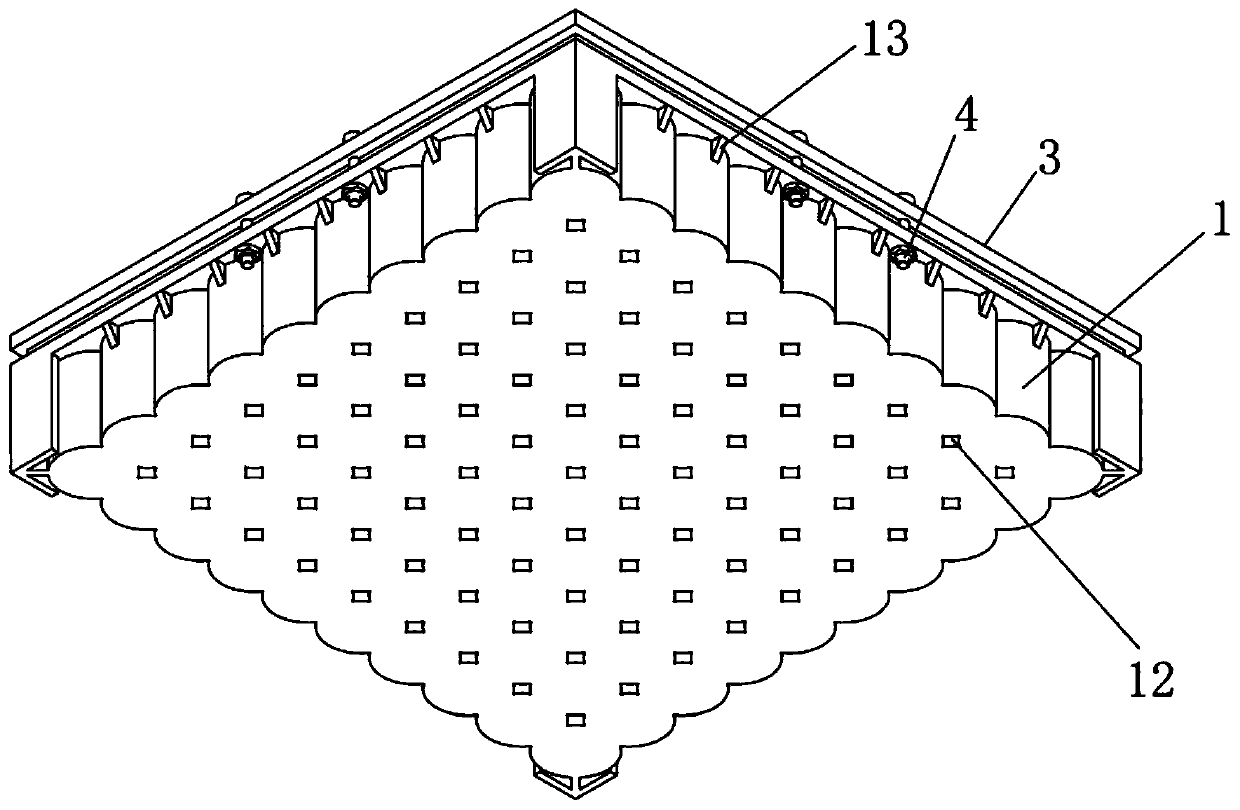
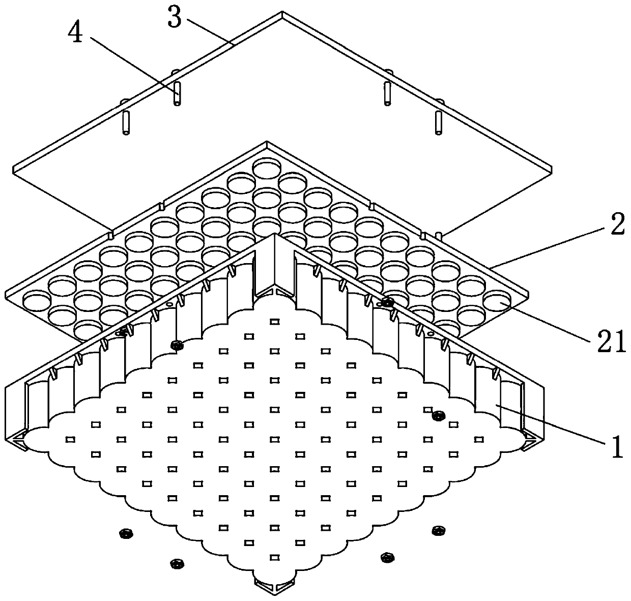
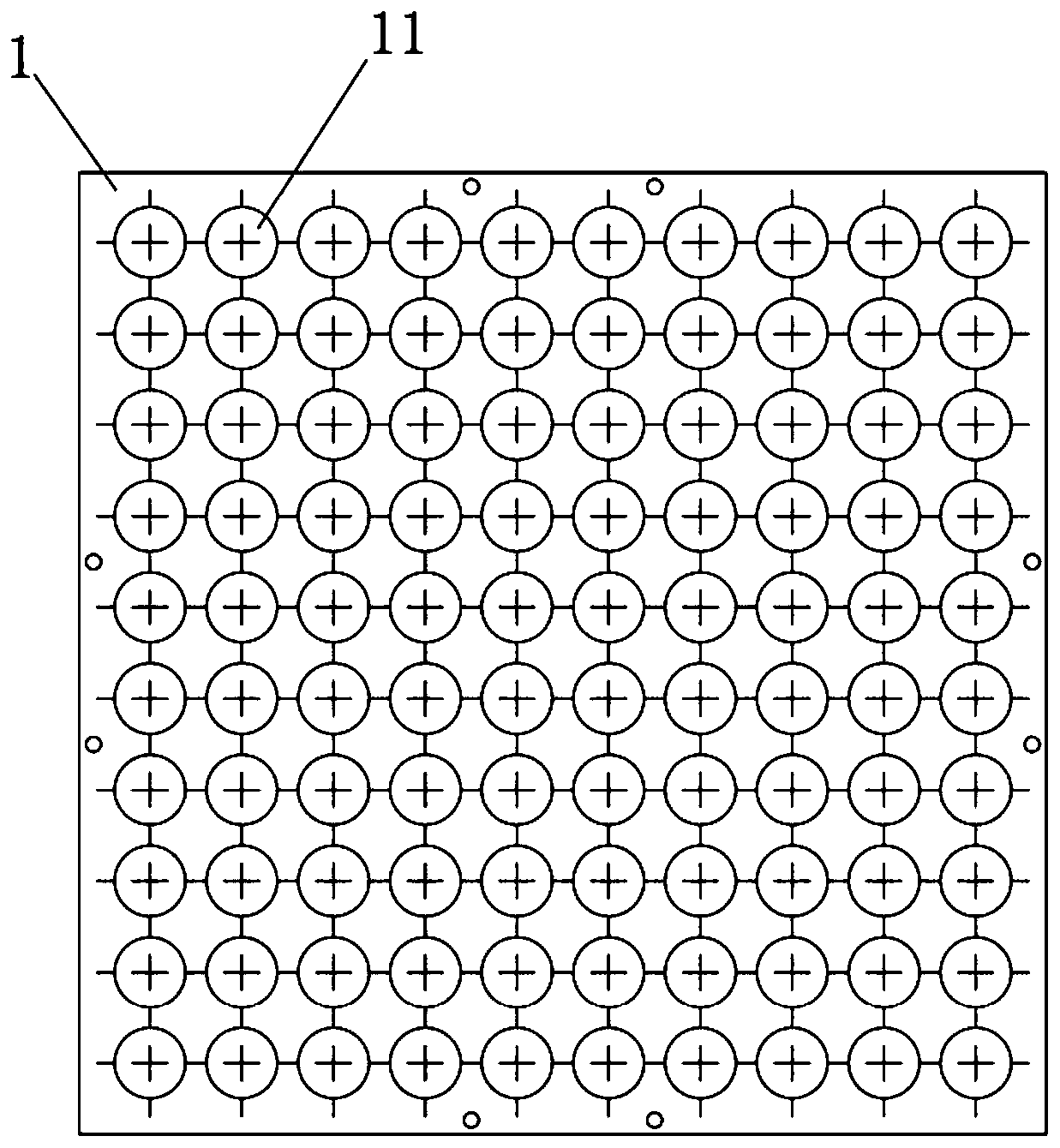
[0026] see Figure 1 to Figure 3 As shown, the high-throughput ceramic microreactor provided by the present invention includes a reactor ceramic main body 1, a rubber gasket 2, and a ceramic cover plate 3. It is solidified, printed and formed, then degreased and sintered, and the sintering temperature is 900°C to 1750°C; the shape and size of the reactor ceramic body 1, rubber gasket 2, and ceramic cover plate 3 match; the reactor ceramic body 1 is There are 4 to 225 reaction microwells 11 distributed in an array, with a spacing of 2 to 5mm, each reaction microwell has a diameter of 5mm to 10mm, and a depth of 10mm to 40mm. Chemical reaction test under corrosive conditions, and different chemical reaction tests can be carried out in different reaction micropores 11; the thickness of the rubber gasket 2 is 1-4mm, laid on the top surface of the reactor ceramic main body 1, and its There are protrusions 21 corresponding to the reaction microholes one by one, and the height of th...

Embodiment 2

[0030] The first step is to use UG software to design a 3*3 9-hole microreactor model. The depth of each hole is 20mm, the hole diameter is 10mm, the hole wall thickness is 2.8mm, and the hole spacing is 3mm. The protrusion diameter of the corresponding rubber gasket is also 10 mm, the protrusion height is 2 mm, and the gasket thickness is 2 mm. The thickness of the ceramic cover plate is 3 mm, and it is fixed with 8 M2 screws, and the screw length is 16 mm. The second step is to export the model to STL format, import the slice into a DLP ceramic light-curing printer to print and shape, and the printing material is zirconia slurry, and the printed green body is as follows: Figure 5 shown. In the third step, put the zirconia microreactor green body in a high-temperature furnace for degreasing and sintering, with a maximum temperature of 1450 degrees, and keep it warm for 2 hours. The fourth step is to prepare 10 mL of Ca(NO3)2·4H2O solution (0.1mol / L), add quantitative (NH4)...


PUM

PropertyMeasurementUnit
Sintering temperatureaaaaaaaaaa
Spacingaaaaaaaaaa
Diameteraaaaaaaaaa

Abstract

The invention discloses a high-flux ceramic micro-reactor. The high-flux ceramic micro-reactor comprises a reactor ceramic main body, a rubber gasket and a ceramic cover plate, and the reactor ceramicmain body and the ceramic cover plate are formed by photocuring printing of ceramic, degreasing and sintering; and the reactor ceramic main body is provided with a plurality of reaction micro-pores,a chemical reaction test under high-temperature and high-pressure or strong-corrosion conditions can be carried out in the reaction micro-pores, the rubber gasket is laid on the top surface of the reactor ceramic main body, bulges in one-to-one correspondence with the reaction micro-pores are formed on the rubber gasket and are used for plugging openings of the reaction micro-pores to ensure the sealing degree of the chemical reaction in the reaction micro-pores and avoid the outward leakage of a reaction liquid in the reaction micro-pores, and the ceramic cover plate covers and presses the rubber gasket and is fixedly connected with the reactor ceramic main body through screws. The high-flux ceramic micro-reactor has the advantages of good high temperature resistance, good acid and alkalicorrosion resistance, good wear resistance, high flux and the like, and is especially suitable for researching micro-reactions at a high temperature, such as a hydrothermal reaction.

Description

technical field [0001] The invention relates to the technical field of ceramic printing and microfluidic synthesis, in particular to a high-throughput ceramic microreactor. Background technique [0002] Microfluidics is the technology and science of manipulating nanoliter to picoliter volume fluids in micron-scale structures. It is a new interdisciplinary subject that has risen rapidly in the past 10 years. Compared with chemical reactions carried out in conventional reaction vessels (flasks or reactors), microfluidic reactors have the characteristics of short intermolecular diffusion distances, large specific surface areas, fast heat and mass transfer rates, and less dosage. At the same time, the high-throughput, large-scale, and parallel characteristics of microfluidic reactors make the integration and parallel operation of multiple or a large number of microreactors possible, thereby improving the efficiency of synthesizing new substances and screening new drugs, and grea...

Claims


Application Information

Patent Timeline
IPC IPC(8): B01J19/00
CPCB01J19/0093
Inventor 施雪涛汤强强李笑宇
Owner SOUTH CHINA UNIV OF TECH
Learn More