Method for roughening metal material surface by using laser shock forming technology and application thereof

A technology of laser shock and forming technology, which is applied in the direction of metal processing equipment, laser welding equipment, welding equipment, etc., can solve the problems of difficult local rough surface preparation and service performance degradation, and achieve accurate and controllable surface roughness and preparation range Effect

Active Publication Date: 2019-12-13
SHANDONG UNIV
View PDF8 Cites 3 Cited by
  • Summary
  • Abstract
  • Description
  • Claims
  • Application Information

AI Technical Summary

Problems solved by technology

[0004] Aiming at the problem that the rough surface prepared by the conventional grinding method is easy to cause the degradation of the service performance, facing the technical obstacle that it is difficult to realize the local rough surface preparation of the metal material, the method proposed by the present invention to rough the surface of the metal material based on the force effect induced by the pulsed laser can Prepare micro-nano structures on the metal surface, and the surface roughness and preparation range are precisely and controllable

Method used


Image

  • Method for roughening metal material surface by using laser shock forming technology and application thereof
  • Method for roughening metal material surface by using laser shock forming technology and application thereof

Examples


Embodiment 1

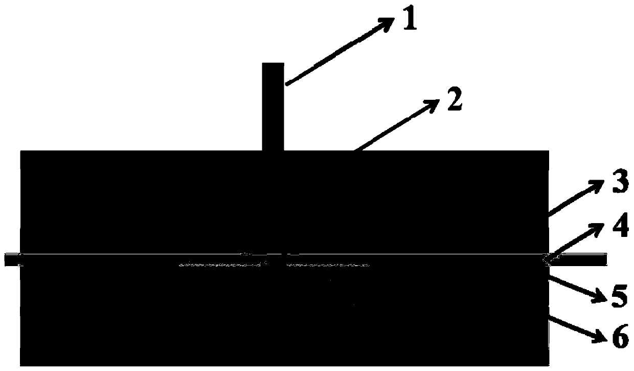
[0046] refer to figure 1 A method for roughening and functionalizing the surface of metal materials by laser shock forming technology, comprising the steps of:

[0047] (1) Preparation of micron imprint mold:

[0048] (1) Select pure aluminum foil as the imprinting mold material, with a thickness of about 0.05 mm; select a pure aluminum plate with a thickness of 2 mm as the surface roughening material, and the surfaces of the pure aluminum foil and the pure aluminum plate have been mechanically polished, and the surface is smooth ;Before laser shock treatment, choose black paint with a thickness of about 0.5mm as the absorbing layer, and choose K9 glass with a thickness of about 3mm as the confinement layer. The parameters of the pulsed laser used are: wavelength 1064nm, energy 1.2J, pulse width A circular beam of 16 ns with a diameter of 2 mm; 200 grit sandpaper was used to prepare the microimprint mold.

[0049] (2) First fix 200-mesh coarse sandpaper 5 on the workbench 6 ...

Embodiment 2

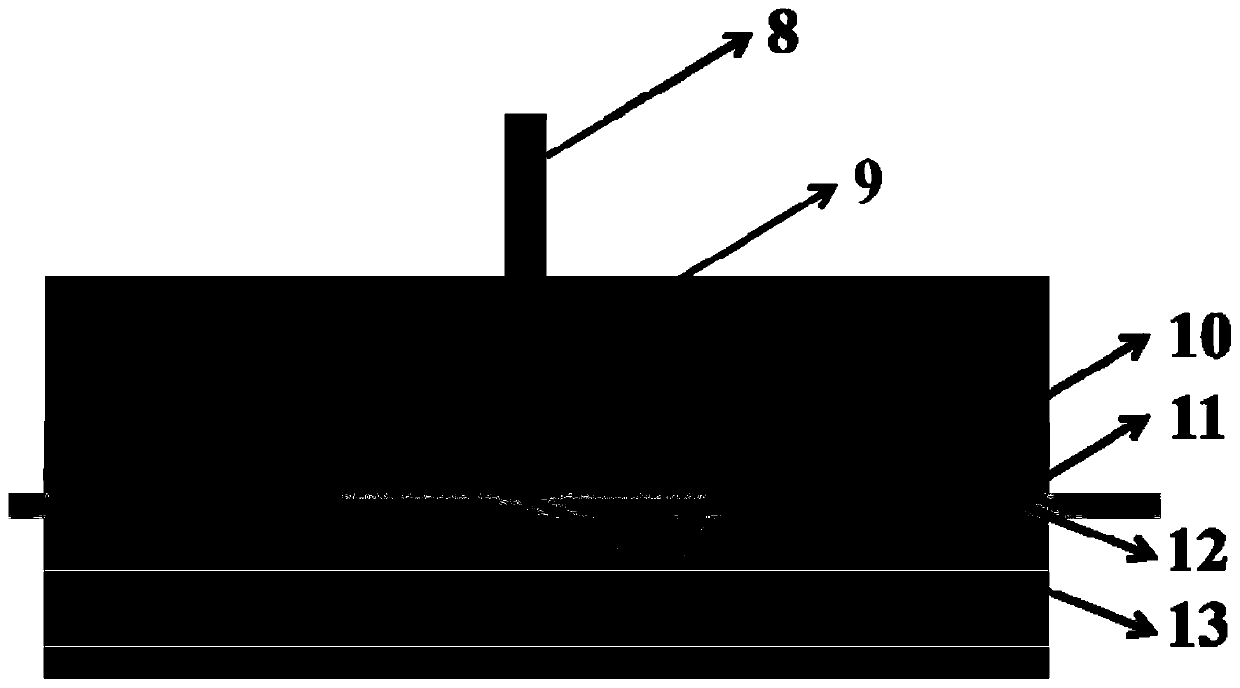
[0067] refer to figure 2 A method for roughening and functionalizing the surface of a metal sheet using laser shock forming technology, comprising the steps of:

[0068] (1) Preparation of micron imprint mold:

[0069] (1) Select pure aluminum foil as the embossing mold material, with a thickness of about 0.05mm; select a pure aluminum sheet with a thickness of 0.45mm as the material to be roughened on the surface, and the surface of the pure aluminum foil and the pure aluminum sheet have been electrochemically Polishing treatment, smooth surface; before laser shock treatment, choose black tape with a thickness of about 0.5mm as the absorbing layer, and choose K9 glass with a thickness of about 3mm as the constraining layer. The parameters of the pulsed laser used are: wavelength 1064nm, energy 3. 2J, a circular beam with a pulse width of 16ns and a diameter of 2mm; 200-mesh coarse sandpaper is used to prepare a micro-imprint mold.

[0070] (2) First fix the pure aluminum f...


PUM

PropertyMeasurementUnit
thicknessaaaaaaaaaa
thicknessaaaaaaaaaa
thicknessaaaaaaaaaa

Abstract

The invention relates to the technical field of metal material surface processing, in particular to a method for roughening a metal material surface by using a laser shock forming technology and an application thereof. According to the method provided based on a pulse laser-induced force effect, after a micro-nano imprinting mold is prepared, the micro-nano imprinting mold is used as a template topresent a surface microstructure of the imprinting mold on the surface of a to-be-machined material, and the method is simple and efficient; and compared with the traditional method, the micro-nano structures can be quantitively prepared on the surface of the metal material, and the surface roughness and the preparation range are precise and controllable and can be pre-designed.

Description

technical field [0001] The invention relates to the technical field of surface processing of metal materials, in particular to a method for roughening and functionalizing the surface of metal materials by laser impact forming technology and its application. Background technique [0002] The information disclosed in the Background of the Invention is only intended to increase the understanding of the general background of the invention, and is not necessarily to be taken as an acknowledgment or any form of suggestion that the information constitutes the prior art that is already known to those skilled in the art. [0003] Superhydrophobic surface refers to a special type of surface layer with an apparent contact angle greater than 150° and a rolling angle less than 10°. The superhydrophobic surface of metal materials has the properties of waterproof and self-cleaning, which can delay the phenomenon of icing and corrosion during the service process of materials. In order to c...

Claims


Application Information

Patent Timeline
Patent Type & Authority Applications(China)
IPC IPC(8): B23K26/00B23K26/352
CPCB23K26/0093B23K26/3568B23K26/356B23K26/3584B23K26/0622B23K26/18
Inventor 卢国鑫季忠王佃刚
Owner SHANDONG UNIV
Why Eureka
Try Eureka