Casting deburring device and working method thereof

A technology for deburring and casting, which is used in grinding drive devices, machine tools suitable for grinding workpiece edges, and manufacturing tools, etc., can solve the problems of many burrs, low efficiency, and high price of deburring machines. Easy to operate, improve work efficiency, simple structure effect

Active Publication Date: 2019-12-13
SHANDONG UNIV OF SCI & TECH
View PDF5 Cites 5 Cited by
  • Summary
  • Abstract
  • Description
  • Claims
  • Application Information

AI Technical Summary

Problems solved by technology

Most of the casting deburring machines currently on the market are complex casting deburring, plus multiple functions such as casting polishing, chamfering, and cleaning. Therefore, a single deburring machine is expensive and is not suitable for simple casting deburring.
[0004] When castings with simple structure are mass-produced, the castings have more burrs. In the prior art, simple castings are usually purely manually deburred, and the efficiency is low. Therefore, a deburring device for simple castings is designed. It is necessary to assist workers

Method used


Image

  • Casting deburring device and working method thereof
  • Casting deburring device and working method thereof
  • Casting deburring device and working method thereof

Examples


Embodiment 1

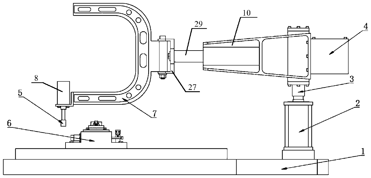
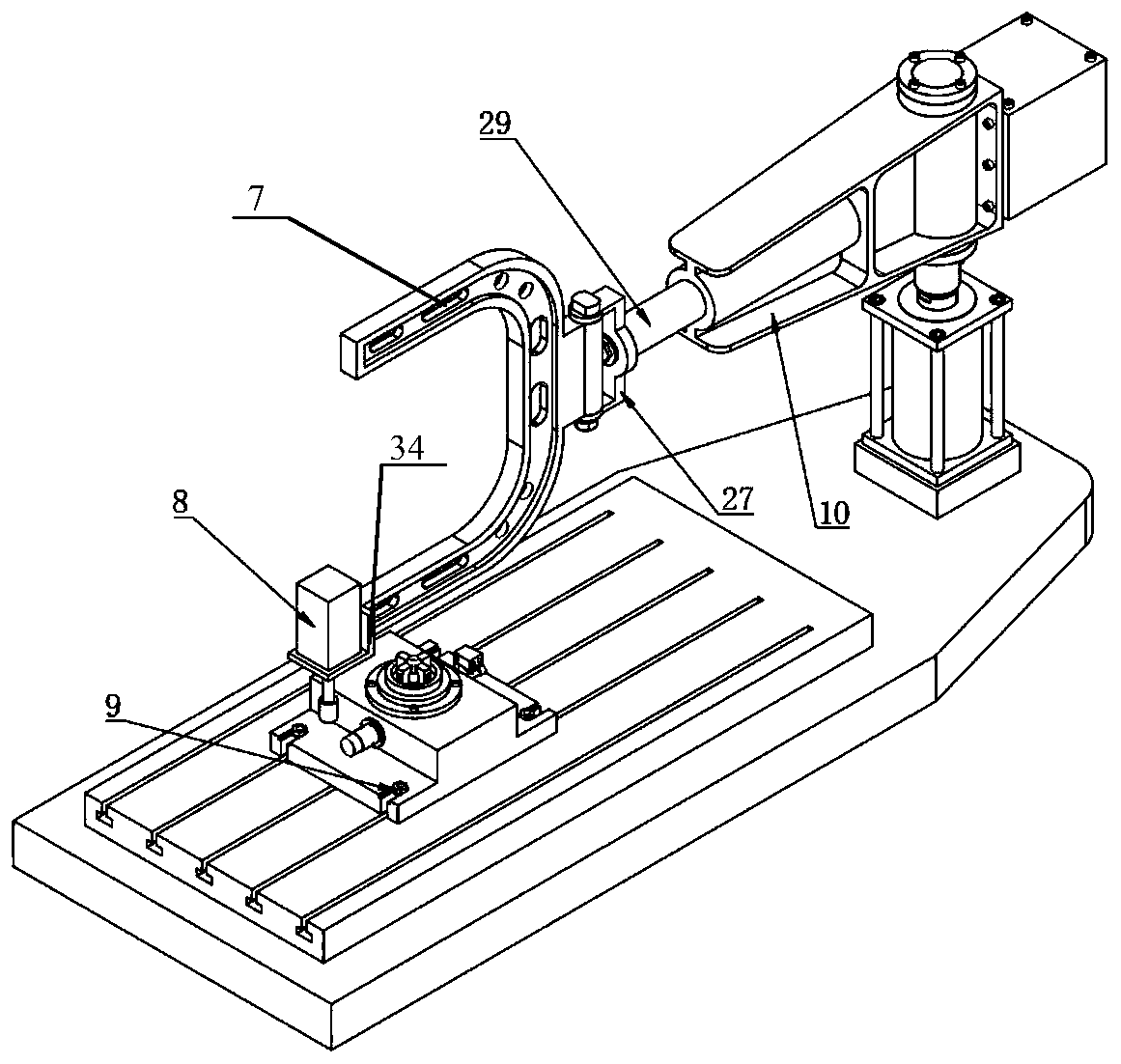
[0043] A casting deburring device, such as Figure 1-7 As shown, it includes a base 1, a clamp body 6 located on one side of the base 1, and a lifting hydraulic cylinder 2 located on the other side of the base 1. The telescopic rod of the lifting hydraulic cylinder 2 is fixedly provided with a main shaft 3, which is rotatably connected to a base Arm 10 and main arm 7, the base arm 10 is fixed on a certain position of the main shaft 3, that is, relatively fixed in the vertical direction, the main arm 7 can move left and right relative to the base arm 10, and can move around the base arm in the horizontal plane 10 free spins;

[0044] The lower end of the main arm 7 is provided with a grinding head 5, the grinding head 5 is driven to rotate by a high-speed motor 8, and the chuck body 6 is used to fix the casting 22 for pre-deburring.

Embodiment 2

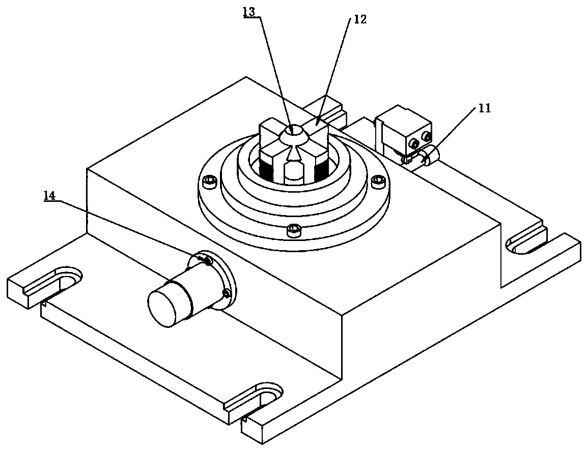
[0046] A casting deburring device, its structure is as shown in embodiment 1, the difference is, as Figure 3-5 As shown, the clamp body 6 includes a clamp body base 15, an end cover 17, an internal expansion body 19 and a traverse hydraulic cylinder 24, the clamp body base 15 and the end cover 17 are fixed on the base 1, and the clamp body base 15 is fixed by the clamp body The bolt 9 is fixed on the base 1, the hydraulic cylinder 24 is fixed on the end cover 17 by the screw 14, the internal expansion body 19 is fixed on the end cover 17, and the telescopic rod of the hydraulic cylinder 24 is connected with a wedge iron push rod 23, The other end of wedge iron push rod 23 is connected with wedge iron 20, and wedge iron 20 is positioned between clamp body base 15 and end cover 17, and end cover 17 is provided with limit hole along the vertical direction, and is provided with push-button hole in limit hole. The rod 21, the bottom of the push rod 21 is in contact with the wedge ir...

Embodiment 3

[0050] A casting deburring device, its structure is as shown in Embodiment 2, the difference is that a free traverse bar 29 is provided between the main arm 7 and the base arm 10, as Figure 6(a) , 6(b) As shown, the base arm 10 is provided with an adjustment passage 28, one end of the free traverse rod 29 is inserted into the adjustment passage 28, and the other end is connected to the main arm 7 through a rotating bracket 27, and the main arm 7 can move laterally relative to the base arm 10 and Rotate in the horizontal plane, the main arm 7 is preferably a U-shaped structure with up and down symmetry, the lower end of the main arm 7 is connected with the grinding head 5, and the upper end can be used for workers to hold and conveniently adjust the position of the grinding head.

[0051] The adjustment channel 28 is non-circular, preferably square, so as to ensure that the free traversing rod can only move left and right, but not rotate.


PUM


Abstract

The invention provides a casting deburring device and a working method thereof and belongs to the technical field of casting deburring. The device comprises a base, a clamp body located on one side ofthe base and a lifting hydraulic cylinder located on the other side of the base, wherein a main shaft is fixedly arranged on a telescopic rod of the lifting hydraulic cylinder, the main shaft is rotationally connected with a base arm and a main arm, the main arm can move left and right relative to the base arm and can rotate around the base arm freely in the horizontal plane, a grinding head is arranged at the lower end of the main arm, the grinding head is driven to rotate by a high-speed motor, and the clamp body is used for fixing a casting to be deburred. The device is simple in structureand can assist workers in deburring, so that the working efficiency is greatly improved.

Description

technical field [0001] The invention relates to a casting deburring device and a working method thereof, belonging to the technical field of casting deburring. Background technique [0002] Castings are metal shaped objects obtained by various casting methods, that is, the smelted liquid metal is poured into the pre-prepared mold by casting method, and after cooling, it is polished and other subsequent processing methods, and the obtained product has a certain shape. Objects of size and performance. Castings are mainly used as blanks for machine parts, and precision castings can also be directly used as machine parts. Castings occupy a large proportion in mechanical products, such as agricultural tractors, castings account for about 50-70% of the weight of the whole machine, and as high as 70-90% in machine tool internal combustion engines. [0003] With the development of society and the advancement of science and technology, the consumption of castings has gradually incr...

Claims


Application Information

Patent Timeline
Patent Type & Authority Applications(China)
IPC IPC(8): B24B9/04B24B27/00B24B41/02B24B41/06B24B47/00B24B47/20B24B47/22B22D31/00
CPCB24B9/04B24B27/0015B24B41/02B24B47/203B24B41/067B24B47/00B24B47/22B22D31/00Y02P70/10
Inventor 万丽荣高冠顺曾庆良逯振国王志文李旭陈一方解鸿博
Owner SHANDONG UNIV OF SCI & TECH
Why Eureka
Try Eureka