[0046] In order to make the objectives, technical solutions and advantages of the present invention clearer, the embodiments of the present invention will be described in further detail below in conjunction with the accompanying drawings.
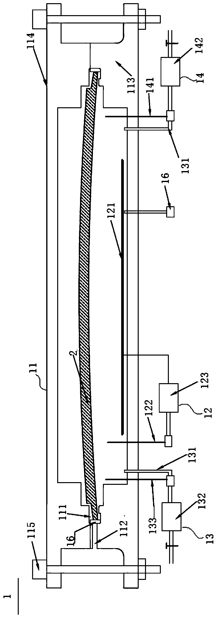
[0047] In an embodiment of the present invention, please refer to figure 1 , Which shows a schematic structural diagram of a edging device 1 applied to glass according to an embodiment of the present invention. The hemming device 1 applied to glass includes a mold 11, a temperature control system 12, a pressure control system 13, and a displacement control system 14, in which:
[0048] The mold 11 has a cavity 111 and at least one injection hole 112 connected to the cavity 111. The mold 11 is used to place the edging substrate 2. The edging substrate 2 can be a flat laminated glass or a curved laminated glass. Glass, but not limited to this. And when the edging base material 2 is placed in the mold 11, its edge is located in the cavity 111, and the cavity 111 is used for accommodating the encapsulation material, so as to edging the edging base material 2 in the cavity 111. At least one injection hole 112 is used to inject an overmolding material into the cavity 111. Please refer again figure 1 The number of at least one glue injection hole 112 disclosed in this embodiment is one, and the glue injection hole 112 is located between the upper mold 114 and the lower mold 113, but it is not limited to this.
[0049] In a preferred embodiment, please refer to figure 1 The mold 11 also includes a lower mold 113, an upper mold 114, and a locking device 115. The lower mold 113 is set on the lower end of the mold 11, the upper mold 114 is set on the lower mold 113, and the edging substrate 2 is placed on the lower mold 113. Yes, a cavity 111 is formed between the upper mold 114 and the lower mold 113, the cavity 111 is located at the edge of the upper mold 114 and the lower mold 113, the locking device 115 is connected to the lower mold 113 and the upper mold 114, and the locking device 115 is used The lower mold 113 and the upper mold 114 are locked and fixed, but the structure of the mold 11 is not limited to this, and those skilled in the art can also choose other suitable structures of the mold 11 according to the teaching of this embodiment. The locking device 115 further disclosed in this embodiment is composed of a plurality of bolt assemblies. The bolts on the plurality of bolt assemblies pass through the upper mold 114 and the lower mold 113 from top to bottom, and are locked and fixed by nuts, so that the upper The mold 114 and the lower mold 113 are locked and fixed, but not limited to this.
[0050] The temperature control system 12 has a heater 121 disposed in the mold 11. The heater 121 disclosed in this embodiment is disposed in the lower mold 113, but it is not limited to this. The heater 121 is used to provide heat to the cavity 111 to heat the encapsulation material and accelerate the curing of the encapsulation material. The heater 121 can be selected as a resistance wire heater or an electromagnetic heater, but it is not limited to this. Please refer again figure 1 The temperature control system 12 further disclosed in this embodiment also has a temperature sensor 122 and a temperature system controller 123. The temperature sensor 122 is disposed in the mold 11, and the temperature sensor 122 is used to sense the temperature in the mold 11 and send a first With feedback signal, the temperature system controller 123 is connected to the heater 121 and the temperature sensor 122. The temperature system controller 123 is used to receive the first feedback signal and control the heating temperature of the heater 121 according to the first feedback signal to realize real-time temperature control. Furthermore, the temperature environment required by the relevant edging materials is maintained, but it is not limited to this.
[0051] The pressure control system 13 has at least one gas path pipe 131 and a pressure controller 132. One end of the at least one gas path pipe 131 communicates with the bottom of the mold 11. One end of the at least one gas pipeline 131 disclosed in this embodiment is connected to the bottom of the lower mold 113, and the encapsulated substrate 2 is ejected by air pressure in the downward mold 113, thereby realizing the demolding of the encapsulated substrate 2 , But not limited to this. This embodiment further discloses that the number of at least one gas path pipe 131 is two, and the two gas path pipes 131 are respectively connected to both sides of the bottom of the lower mold 113, but it is not limited thereto.
[0052] The other end of the at least one gas path pipe 131 is connected to a pressure controller 132, and the pressure controller 132 can provide air pressure into the mold 11 through the at least one gas path pipe 131 to demold the hemming substrate 2. Please refer again figure 1 The pressure control system 13 disclosed in this embodiment also has a pressure sensor 133, which is arranged in the mold 11 and is connected to the pressure controller 132. The pressure sensor 133 is used to sense the pressure value of the air pressure in the mold 11 and provide The controller 132 sends a second feedback signal, and the pressure controller 132 adjusts the air pressure according to the second feedback signal to achieve real-time air pressure control, but it is not limited to this.
[0053] The displacement control system 14 has a displacement sensor 141 and a displacement controller 142. The displacement sensor 141 is arranged in the mold 11 and is connected to the displacement controller 142. The displacement controller 142 is connected to the pressure controller 132. The displacement sensor 141 is used for sensing. The displacement of the edging substrate 2 is measured and sent to the displacement controller 142. The displacement controller 142 also has a demolding displacement parameter. When the displacement of the edging substrate 2 is greater than the demolding displacement parameter, the displacement controller 142 It is fed back to the pressure controller 132, and the pressure controller 132 is controlled to stop providing air pressure and realize displacement control.
[0054] In a preferred embodiment, the edging device 1 applied to glass further includes a pressure relief valve 15 and a plurality of edge blocks 16. The pressure relief valve 15 is connected to the lower end of the mold 11, and the pressure relief valve 15 is used to complete the demolding process. After that, the air pressure in the mold 11 is released, and a plurality of side rest blocks 16 are used for the installation and positioning of the edging base material 2, but it is not limited to this.
[0055] When the edging device 1 applied to glass of this embodiment is edging, the relative position of the edging base material can be determined by a plurality of edge rest blocks 16. After the glue injection is completed, the pressure control system 13 controls the edging material Curing temperature, during demolding, the demolding pressure and displacement speed are controlled by the pressure control system 13, and the displacement distance is controlled by the displacement control system 14, to achieve rapid curing and rapid demolding of the encapsulation material, and the application of this embodiment to glass The edging device 1 can be used for edging structural glass of different curvatures and shapes, with high efficiency and strong practicability.
[0056] In the two embodiments of the present invention, please refer to figure 2 and figure 1 , figure 2 It shows a schematic flow chart of the steps of the edging method 3 applied to glass according to the second embodiment of the present invention. The edging method applied to glass includes the following steps 301-308, among which:
[0057] In step 301, the edging substrate 2 is placed. The edging base material 2 is placed in the mold 11 with the edges in the cavity 111.
[0058] Specifically, the upper mold 114 is opened, a plurality of side leaning blocks 16 are placed in the lower mold 113, and the edging substrate 2 is placed in the lower mold 113 along the edges of the plurality of side leaning blocks 16, and the side portions are taken out Lean against the block 16 and close the upper mold 114 and the lower mold 113, close the upper mold 114 and the lower mold 113, and use the locking device 115 to lock and fix the upper mold 114 and the lower mold 113. Preferably, the parting surface of the upper mold 114 and the lower mold 113 is less than 0.05 mm, but it is not limited thereto.
[0059] Step 302, injection molding of the overmolding material. An overmolding material is injected into the cavity 111.
[0060] Specifically, the injection molding machine is connected to the injection hole 14, and the encapsulation material is injected into the cavity 111 through the injection hole 14, and the injection is stopped after being filled, but it is not limited to this.
[0061] Step 303, heating and curing. Turn on the temperature control system 12, set the heating temperature of the heater 121, heat and solidify the encapsulation material, and keep it warm.
[0062] Specifically, the temperature control system 12 is turned on, and the heating temperature of the heater 121 is set according to the process requirements, preferably 40-60 degrees Celsius, but not limited to this. The cavity 111 is heated by the heater 121, and then the encapsulating material is heated and cured, and kept warm. The heat preservation time is preferably 4-6 hours, but is not limited thereto.
[0063] Step 304, remove the upper mold 114. The temperature control system 12 is closed, and the upper mold 114 is removed.
[0064] Specifically, the temperature control system 12 is closed, the locking device 115 is released, and the upper mold 114 is removed, but it is not limited to this.
[0065] Step 305: Set demolding parameters. The pressure control system 13 is turned on, and the gas pressure value and the demolding pressure parameter of the edging substrate 2 are set.
[0066] Specifically, after opening the pressure sensor 133 and the pressure controller 132, set the gas pressure value, preferably 0.4-0.6 MPa; set the demolding pressure parameter of the edging substrate 2, preferably less than or equal to 30 kPa, but Not limited to this.
[0067] Step 306: Set displacement parameters. The displacement control system 14 is turned on, and the demolding displacement parameter of the edging substrate 2 is set.
[0068] Specifically, the displacement controller 142 is turned on, and the demolding displacement parameter of the edging substrate 2 is set, preferably less than or equal to 3 mm, but not limited to this.
[0069] Step 307, demoulding. Compressed air is filled into the lower mold 113, and the displacement control system 14 detects the displacement of the edging substrate 2. When the displacement of the edging substrate 2 is greater than the demolding displacement parameter, the inflation is stopped and demolding is completed.
[0070] Specifically, the lower mold 113 is filled with compressed air, and the displacement control system 14 detects the displacement of the edging substrate 2. When the displacement of the edging substrate 2 is greater than the set value, the inflation is stopped and demolding is completed, but the Not limited to this.
[0071] Step 308, take out the edging substrate 2 to complete the edging.
[0072] Specifically, the edging substrate 2 is taken out from the lower mold 113 with a suction cup to obtain the edging substrate 2 that has been encapsulated, but it is not limited to this.
[0073] The edging method 3 applied to glass of this embodiment determines the relative position of the edging base material by a plurality of edge supporting blocks 16. After the glue injection is completed, the pressure control system 13 controls the curing temperature of the edging material, and when demolding , The demolding pressure and displacement speed are controlled by the pressure control system 13, and the displacement distance is controlled by the displacement control system 14, to achieve rapid curing and rapid demolding of the encapsulating material, and the encapsulation device 1 applied to glass of this embodiment is available The edging structure glass of different curvature and shape has high efficiency and strong practicability.
[0074] The above description shows and describes several preferred embodiments of the present invention, but as mentioned above, it should be understood that the present invention is not limited to the form disclosed herein, and should not be regarded as the exclusion of other embodiments, but can be used for each Other combinations, modifications, and environments can be modified through the above teachings or technology or knowledge in related fields within the scope of the inventive concept described herein. However, modifications and changes made by those skilled in the art do not depart from the spirit and scope of the present invention, and should fall within the protection scope of the appended claims of the present invention.