Three-dimensional hydraulic jacking machine and three-dimensional jacking system

A jacking machine and hydraulic technology, applied in the direction of lifting devices, etc., can solve the problems of limited movement range of hydraulic jacks, inability to be moved by jacking equipment in multiple directions, and inability to adapt, so as to achieve flexible lifting, improve convenience and practicability , Improve the effect of pushing tonnage

Pending Publication Date: 2019-12-13
常州瑞阳液压成套设备有限公司
View PDF0 Cites 7 Cited by
  • Summary
  • Abstract
  • Description
  • Claims
  • Application Information

AI Technical Summary

Problems solved by technology

[0004] In order to solve the problem that the hydraulic jacks in the prior art cannot move the lifted equipment in multiple directions, the range of motion of the hydraulic jack itself is also limited, it is difficult to realize the lifting of multiple hydraulic jacks, and it cannot adapt to the operation and development of large-scale installation projects at present. technical problems, the present invention provides a three-dimensional hydraulic jack to solve the above problems

Method used


Image

  • Three-dimensional hydraulic jacking machine and three-dimensional jacking system
  • Three-dimensional hydraulic jacking machine and three-dimensional jacking system
  • Three-dimensional hydraulic jacking machine and three-dimensional jacking system

Examples


Embodiment 1

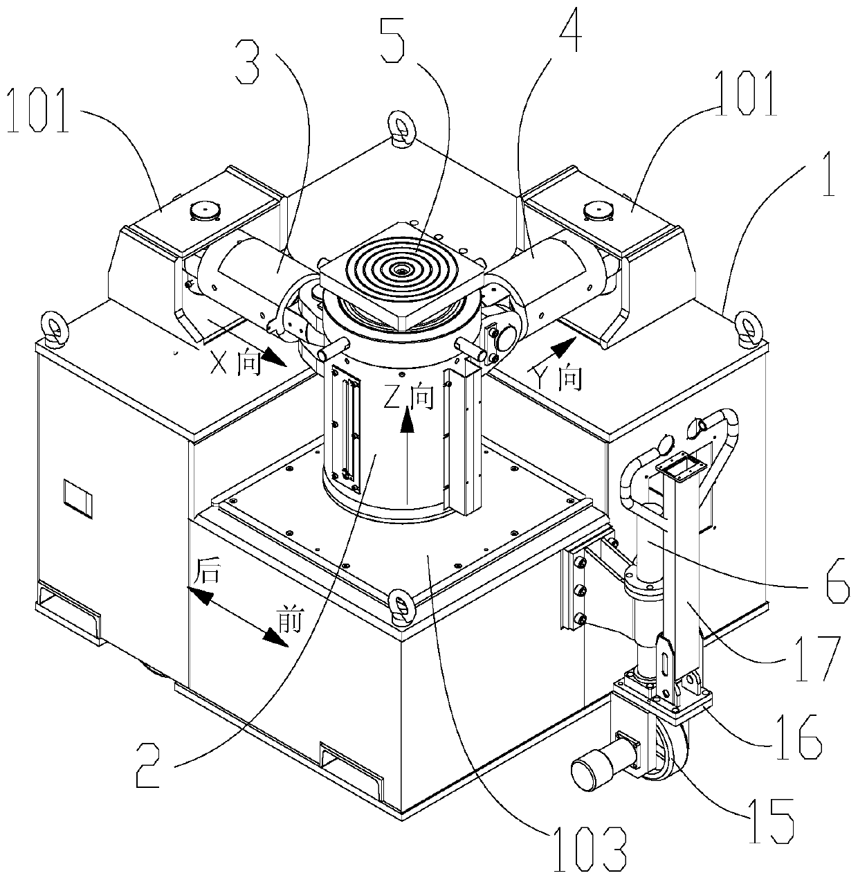
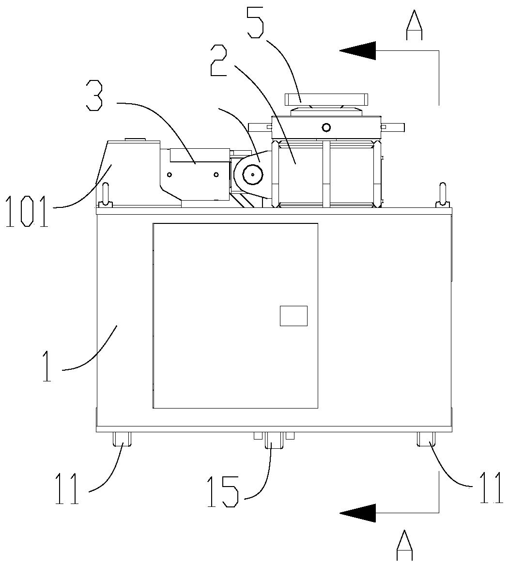
[0052] Example 1, such as Figure 1-Figure 5 As shown, a three-dimensional hydraulic jacking machine includes a vehicle frame 1, a main cylinder 2 located on the top of the vehicle frame 1 and adapted to slide horizontally along the surface of the vehicle frame 1, and a first side located on the circumferential side of the main cylinder 2 To the oil cylinder 3 and the second side oil cylinder 4, and the road wheel assembly suitable for driving the vehicle frame 1 to walk. The vehicle frame 1 has an approximate square structure, and the main oil cylinder 2, the first lateral oil cylinder 3 and the second lateral oil cylinder 4 all adopt high-pressure oil cylinders, and the system pressure is generally 70-80 MPa.

[0053] One end of the first lateral oil cylinder 3 and the second lateral oil cylinder 4 away from the main oil cylinder 2 are both connected to the vehicle frame 1; The oil cylinder 4 expands and contracts along the Y direction. The traveling wheel assembly is used...

Embodiment 2

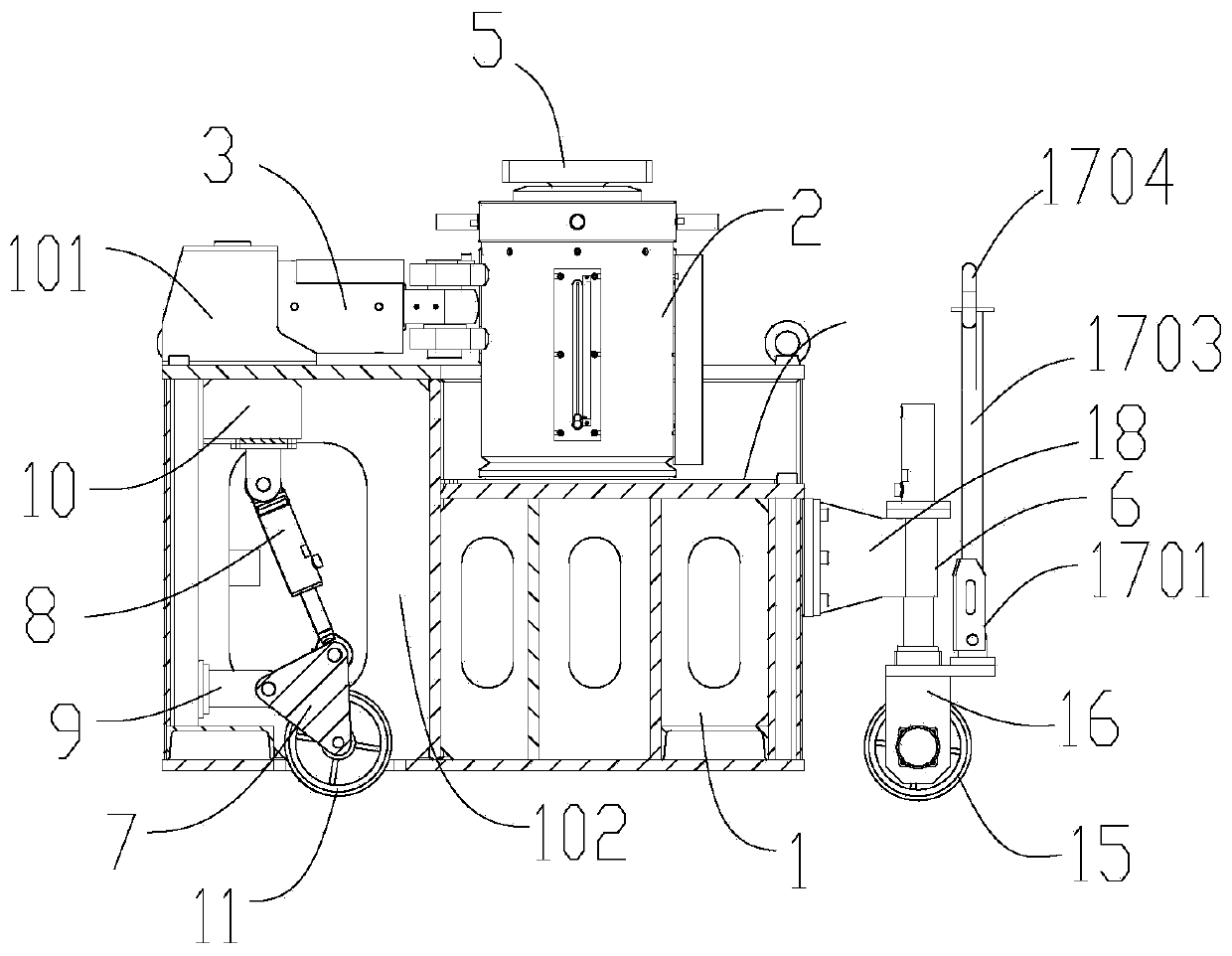
[0061] Embodiment 2, on the basis of embodiment 1, as Figure 3-Figure 6 As shown, the top of the main oil cylinder 2 is provided with a ball seat assembly 5, and the ball seat assembly 5 includes a ball seat 502, a ball head 501 and a fixed column 503 connecting the ball seat 502 and the ball head 501, the ball seat 502 and the main ball seat 502 One axial end of the oil cylinder 2 is fixed, the other end of the main oil cylinder 2 is placed on the vehicle frame 1, the upper surface of the ball head 501 is in contact with the equipment to be lifted, the contact surface between the ball seat 502 and the ball head 501 is a spherical surface, and the ball head 501 can move relative to the ball seat 502 along the spherical surface, and the fixed column 503 connects the ball head 501 and the ball seat 502 axially, and has a small axial movement space. Any rotational movement. When pushing the hull, the ball head 501 can produce a small angle change, which is beneficial to fit the...

Embodiment 3

[0063] Embodiment 3, a kind of three-dimensional hydraulic jacking machine, such as figure 1 , figure 2 As shown, it includes a vehicle frame 1, a main oil cylinder 2 located on the top of the vehicle frame 1 and adapted to slide horizontally along the surface of the vehicle frame 1, a first lateral oil cylinder 3 and a second lateral oil cylinder located on the peripheral side of the main oil cylinder 2 Oil cylinder 4, and the walking wheel assembly suitable for driving vehicle frame 1 to walk. The vehicle frame 1 has an approximate square structure, and the main oil cylinder 2, the first lateral oil cylinder 3 and the second lateral oil cylinder 4 all adopt high-pressure oil cylinders, and the system pressure is generally 70-80 MPa.

[0064] One end of the first lateral oil cylinder 3 and the second lateral oil cylinder 4 away from the main oil cylinder 2 are both connected to the vehicle frame 1; The oil cylinder 4 expands and contracts along the Y direction.

[0065] S...


PUM


Abstract

The invention discloses a three-dimensional hydraulic jacking machine and a three-dimensional jacking system. The three-dimensional hydraulic jacking machine comprises a frame, a main oil cylinder located on the top of the frame and suitable for sliding horizontally along the surface of the frame, a first lateral oil cylinder and a second lateral oil cylinder located on the circumferential side face of the main oil cylinder and a walking wheel assembly suitable for driving the frame to walk. One ends of the first lateral oil cylinder and the second lateral oil cylinder far away from the main oil cylinder are connected to the frame; and the main oil cylinder stretches along a Z direction, the first lateral oil cylinder stretches along an X direction and the second lateral oil cylinder stretches along a Y direction. The three-dimensional hydraulic jacking machine is compact in structure and flexible to lift, and multiple three-dimensional hydraulic jacking machines can be matched to operate to improve the lifting tonnage, so that the three-dimensional hydraulic jacking machine is suitable for centering and folding work of subsections of ship bodies and bridges and large steel structural parts.

Description

technical field [0001] The invention relates to special hydraulic equipment, which belongs to the field of installation of ship hull bridge sections and large steel structure parts, and in particular relates to a three-dimensional hydraulic jacking machine and a three-dimensional jacking system. Background technique [0002] The three-dimensional hydraulic jacking machine is mainly used for the lifting and centering of the hull bridge section and the closing operation of large steel structure parts. The cooperation of multiple units can lift and move the hull bridge section and large steel structure parts to complete the hull bridge Centering and closing work of segments and large steel structures. [0003] In recent years, the weight of hull bridge sections and large steel structural parts has been increasing, and the function and lifting capacity of the equipment used for installation have also increased. important factor in development. Traditional hydraulic jacks are o...

Claims


Application Information

Patent Timeline
Patent Type & Authority Applications(China)
IPC IPC(8): B66F3/24B66F3/46
CPCB66F3/24B66F3/46
Inventor 汪强韩礼云王雪丽
Owner 常州瑞阳液压成套设备有限公司
Why Eureka
Try Eureka