Arc-shaped terrace beam sluice gate with layered water intake function and working method thereof

A technology of stacked beam gates and layered water intake, applied in water conservancy projects, sea area projects, water supply devices, etc., can solve problems such as high surface water temperature, unfavorable water plant treatment, unfavorable crop growth, etc., and achieve the effect of simple structure

Pending Publication Date: 2019-12-13
JIANGSU PROVINCE WATER ENG SCI TECH CONSULTING
View PDF0 Cites 6 Cited by
  • Summary
  • Abstract
  • Description
  • Claims
  • Application Information

AI Technical Summary

Problems solved by technology

[0002] The investigation of the data of the built water conservancy and hydropower projects shows that the deep reservoir and high dam with multi-year regulation performance have obvious vertical stratification of reservoir water temperature, the surface water temperature is high, the deep water temperature is low, and some mineral indicators in the deep water exceed the standard, which has a certain stench , deep water intake cannot provide high-quality water sources, and it is difficult to guarantee the quality of water supply
[0003] The main function of the reservoir is water supply and irrigation. The gravity flow pressure pipeline is used for water delivery. The low temperature and low turbidity water in the lower part of the reservoir is not conducive to the treatment of the water plant and is not conducive to the growth of crops.

Method used


Image

  • Arc-shaped terrace beam sluice gate with layered water intake function and working method thereof
  • Arc-shaped terrace beam sluice gate with layered water intake function and working method thereof
  • Arc-shaped terrace beam sluice gate with layered water intake function and working method thereof

Examples


Embodiment Construction

[0051] 下面结合附图以及附图说明,对本发明做进一步说明。

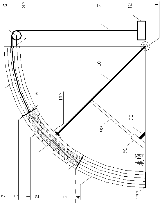
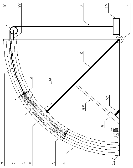
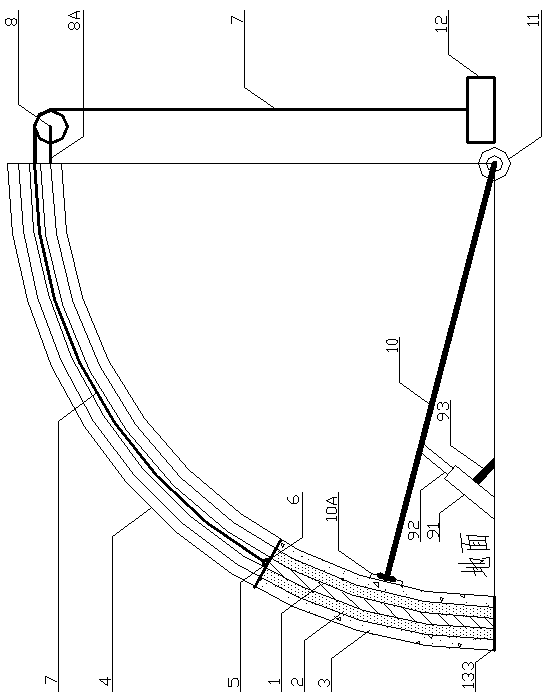
[0052] 一种具有分层取水功能的弧形叠梁闸门,包括弧形叠梁闸门、弧形闸门槽4、定滑轮8、液压启闭机9、转轴11、启闭杆10、电动机12,弧形叠梁闸门包括第一弧形子闸门1、第二弧形子闸门2、第三弧形子闸门3。在第三弧形子闸门3上设有可容第二弧形子闸门2插入的第三空腔,第二弧形子闸门2上设有可容第一弧形子闸门1插入的第二空腔,第一弧形子闸门1插于第二弧形子闸门2的第二空腔,第二弧形子闸门2插于第三弧形子闸门3的第三空腔。在第一弧形子闸门1底部左右两侧各设置一第一钢板1A,当第一弧形子闸门1沿第二弧形子闸门2第二空腔移动时,在第一钢板1A作用下,第一弧形子闸门1无法从第二空腔的开口处抽出。在第二弧形子闸门1底部左右两侧各设置一第二钢板1A,当第二弧形子闸门1沿第三弧形子闸门2第三空腔移动时,在第二钢板1A作用下,第二弧形子闸门1无法从第三空腔的开口处抽出。

[0053] 第三弧形子闸门3的侧边置于弧形闸门槽4内,定滑轮8设置在弧形闸门槽4的后部;电动机12的动力输出轴与吊绳7固定连接,吊绳7的一端缠绕于电动机12的动力输出轴上,另一端经定滑轮8后固定于第一弧形子闸门1的顶部。

[0054] 将液压启闭机9设置于弧形叠梁闸门下游侧地面上,液压启闭机9包括液压油缸91、活塞杆92和支撑杆93,液压启闭机9的动力来源于液压油缸91;活塞杆92一端连接液压油缸91,另一端连接启闭杆10;支撑杆93底部倾斜设置在地面上,支撑杆93顶端设置在液压油缸91中部,用于支撑液压油缸91。

[0055] 在第三弧形子闸门3最外侧表面中部设置承接板10A,转轴11固定于弧形叠梁闸门下游侧地面上;启闭杆10顶端连接承接板10A,底部连接转轴11,通过液压启闭机9和转轴11带动启闭杆10转动,进而控制弧形叠梁闸门的移动。

[0056] 进一步的,弧形闸门槽4为钢筋混凝土结构。定滑轮8通过钢条8A固定弧形闸门槽4上。在第一弧形子闸门1顶部中间段设置两个吊耳6,两个吊耳6呈左右对称形式;吊绳7与第一弧形子闸门1连接的一端设有与吊耳6相匹配的吊钩5,吊钩5钩于吊耳6上。在电动机12的动力输出轴上设置卷筒,吊绳7的一端固定于卷筒上,且吊绳7缠绕于电动机12的动力输出轴上的卷筒上。在第一弧形子闸门1、...


PUM


Abstract

The invention relates to an arc-shaped terrace beam sluice gate with a layered water intake function and a working method thereof. The sluice gate comprises the arc-shaped terrace beam sluice gate, anarc-shaped sluice gate slot, a fixed pulley, a hydraulic hoist, a rotating shaft, a hoist rod and an electric motor; the arc-shaped terrace beam sluice gate comprises a first arc-shaped sub sluice gate, a second arc-shaped sub sluice gate and a third arc-shaped sub sluice gate; and the third arc-shaped sub sluice gate is provided with a third cavity which can accommodate the insertion of the second arc-shaped sub sluice gate, the second arc-shaped sub sluice gate is provided with a second cavity which can accommodate the insertion of the first arc-shaped sub sluice gate, the first arc-shapedsub sluice gate is inserted into the second cavity of the second arc-shaped sub sluice gate, and the second arc-shaped sub sluice gate is inserted into the third cavity of the third arc-shaped sub sluice gate. According to the arc-shaped terrace beam sluice gate with the layered water intake function, the overall movement of the terrace beam sluice gate is controlled through the hydraulic hoist, lifting of the first arc-shaped sub sluice gate is controlled through the electric motor, and layered water intake and surface water intake of the arc-shaped terrace beam sluice gate are realized. Thehydraulic hoist is used for controlling whole movement of the terrace beam sluice gate to the height of flood scouring and silting, and a function of flood scouring and silting of the terrace beam sluice gate is realized.

Description

technical field [0001] The invention relates to an arc stacked beam gate with layered water intake function and a working method thereof, belonging to the field of hydraulic engineering equipment. Background technique [0002] The investigation of the data of the built water conservancy and hydropower projects shows that the deep reservoir and high dam with multi-year regulation performance have obvious vertical stratification of reservoir water temperature, the surface water temperature is high, the deep water temperature is low, and some mineral indicators in the deep water exceed the standard, which has a certain stench , Deep water intake cannot provide high-quality water sources, and it is difficult to guarantee the quality of water supply. [0003] The main functions of the reservoir are water supply and irrigation, and the gravity flow pressurized pipeline is used for water delivery. The low temperature and low turbidity water in the lower part of the reservoir is not...

Claims


Application Information

Patent Timeline
Patent Type & Authority Applications(China)
IPC IPC(8): E02B7/22E02B7/42E02B7/54E03B3/04
CPCE02B7/22E02B7/42E02B7/54E03B3/04
Inventor 沈颖孙晨光翟高勇吴玲玲丁鑫洪颜凝香孙伯明
Owner JIANGSU PROVINCE WATER ENG SCI TECH CONSULTING
Why Eureka
Try Eureka