A high-pressure pump cooling mechanism

A cooling mechanism and pump technology, applied in mechanical equipment, machines/engines, liquid variable capacity machinery, etc., to achieve the effect of improving heat dissipation, good heat dissipation, and protecting the stability of use

Active Publication Date: 2020-12-18
嘉兴恒益安全服务股份有限公司
View PDF6 Cites 0 Cited by
  • Summary
  • Abstract
  • Description
  • Claims
  • Application Information

AI Technical Summary

Problems solved by technology

[0004] Aiming at the deficiencies in the use of the existing high-pressure pump proposed in the background technology, the present invention provides a high-pressure pump cooling mechanism, which has the advantages of good cooling and heat dissipation effect and longer service life of the rubber piston, and solves the problem of Problems raised in the background art above

Method used


Image

  • A high-pressure pump cooling mechanism
  • A high-pressure pump cooling mechanism
  • A high-pressure pump cooling mechanism

Examples


Embodiment Construction

[0017] The following will clearly and completely describe the technical solutions in the embodiments of the present invention with reference to the accompanying drawings in the embodiments of the present invention. Obviously, the described embodiments are only some, not all, embodiments of the present invention. Based on the embodiments of the present invention, all other embodiments obtained by persons of ordinary skill in the art without making creative efforts belong to the protection scope of the present invention.

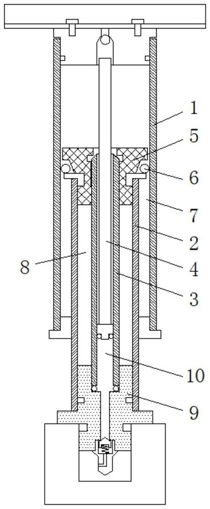
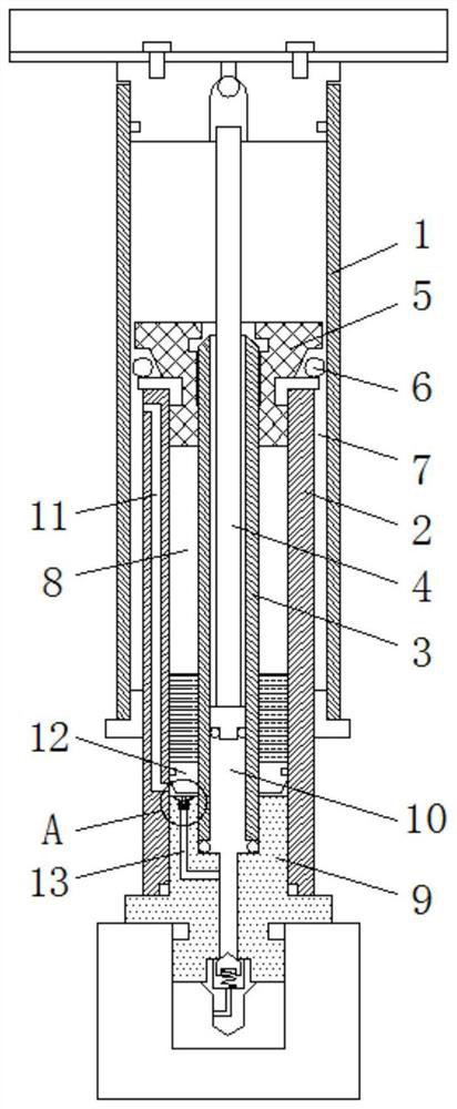
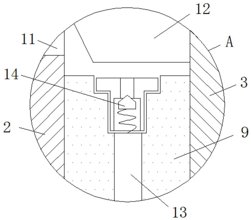
[0018] see Figure 1-3 , a cooling mechanism for a high-pressure air pump, comprising an outer cylinder 1, an inner cylinder 2 and a three-stage compression cylinder 3, the outer cylinder 1, the inner cylinder 2 and the three-stage compression cylinder 3 are sequentially socketed inwardly, and the three-stage compression The piston rod 4 is movably socketed in the cylinder 3, the top ends of the outer cylinder 1 and the piston rod 4 are fixedly connected to th...


PUM


Abstract

The invention relates to the technical field of cooling of inflators and discloses a cooling mechanism for a high-pressure inflator. The cooling mechanism comprises an outer cylinder barrel, an innercylinder barrel, a first-stage compression chamber, an air storage chamber, a pedestal and a third-stage compression chamber; the bottom of the air storage chamber is provided with cooling liquid; thecooling liquid can move with up-and-down movement of the outer cylinder barrel; the inside of the air storage chamber is slidably connected with a liquid isolating plug; the liquid isolating plug ispositioned below the cooling liquid; the inner wall of the inner cylinder barrel is provided with a compensative air channel; the inner wall of the pedestal is provided with an inflating channel; andthe top end of the inflating channel is provided with a one-way pneumatic valve. According to the cooling mechanism disclosed by the invention, the air storage chamber is filled with the cooling liquid so that the high temperature at a third-stage compression cylinder can be transmitted to the inner cylinder barrel in time; the outer wall of the inner cylinder barrel makes direct contact with theatmosphere, so the cooling mechanism achieves a relatively good heat radiation effect, the heat inside the third-stage compression cylinder can be quickly transmitted, and thus the use stability of apiston inside the third-stage compression cylinder can be protected preferably.

Description

technical field [0001] The invention relates to the technical field of air pump heat dissipation, in particular to a high-pressure air pump cooling mechanism. Background technique [0002] The high-pressure pump adopts a three-stage compressed gas sleeve structure, which can realize manual high-pressure inflation, and cooperates with the high-pressure thin tube structure on the upper inner layer, and uses high pressure and low stress area to achieve the effect of small resistance, which can realize labor-saving function and is widely used Used in manual and portable pumps. [0003] Such as figure 1 As shown, the outer cylinder 1 is lifted up to replenish the gas, and then pressed down, the gas enters the first-stage compression chamber 7 through the one-way air intake apron 6, and then the outer cylinder 1 is lifted up, and the one-way air intake apron 6 is blocked The gap between the top cover 5 and the outer cylinder 1, the gas enters the gas storage chamber 8, then ente...

Claims


Application Information

Patent Timeline
Patent Type & Authority Patents(China)
IPC IPC(8): F04B39/06
CPCF04B39/06
Inventor 陈瑞中
Owner 嘉兴恒益安全服务股份有限公司
Why Eureka
Try Eureka