
High-flow pressure relief device of medical gas

A decompression device and high-flow technology, applied in gas/liquid distribution and storage, pipeline systems, mechanical equipment, etc., can solve problems such as increased safety hazards, pressure gauge deviation, poor stability of the decompression box, etc., to reduce accidents The incidence rate, avoid bending deformation, and the effect of not easy to leak

Active Publication Date: 2019-12-13
ZHEJIANG QIANGSHENG MEDICAL ENG
View PDF5 Cites 0 Cited by
  • Summary
  • Abstract
  • Description
  • Claims
  • Application Information

AI Technical Summary

Problems solved by technology

When the pressure gauge is installed, the verticality of the pressure gauge should be ensured as much as possible, but in the prior art, there will still be a large deviation during the installation process of the pressure gauge, which will affect the test accuracy of the pressure value
Moreover, when the existing decompression box is installed, it is generally placed directly in the tube well, which makes the stability of the decompression box poor and increases potential safety hazards.

Method used


Image

  • High-flow pressure relief device of medical gas
  • High-flow pressure relief device of medical gas
  • High-flow pressure relief device of medical gas

Examples


Embodiment Construction

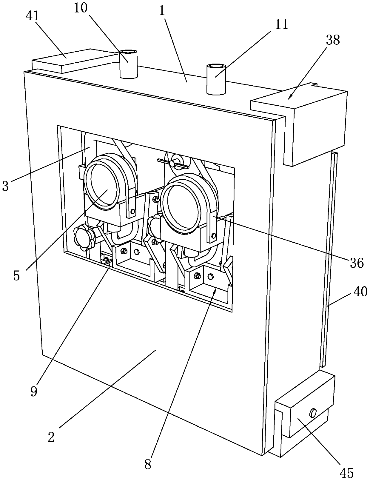
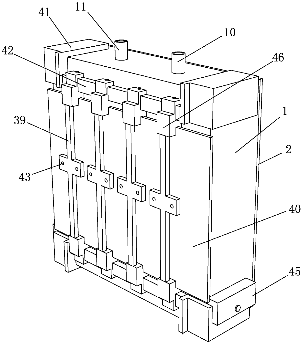
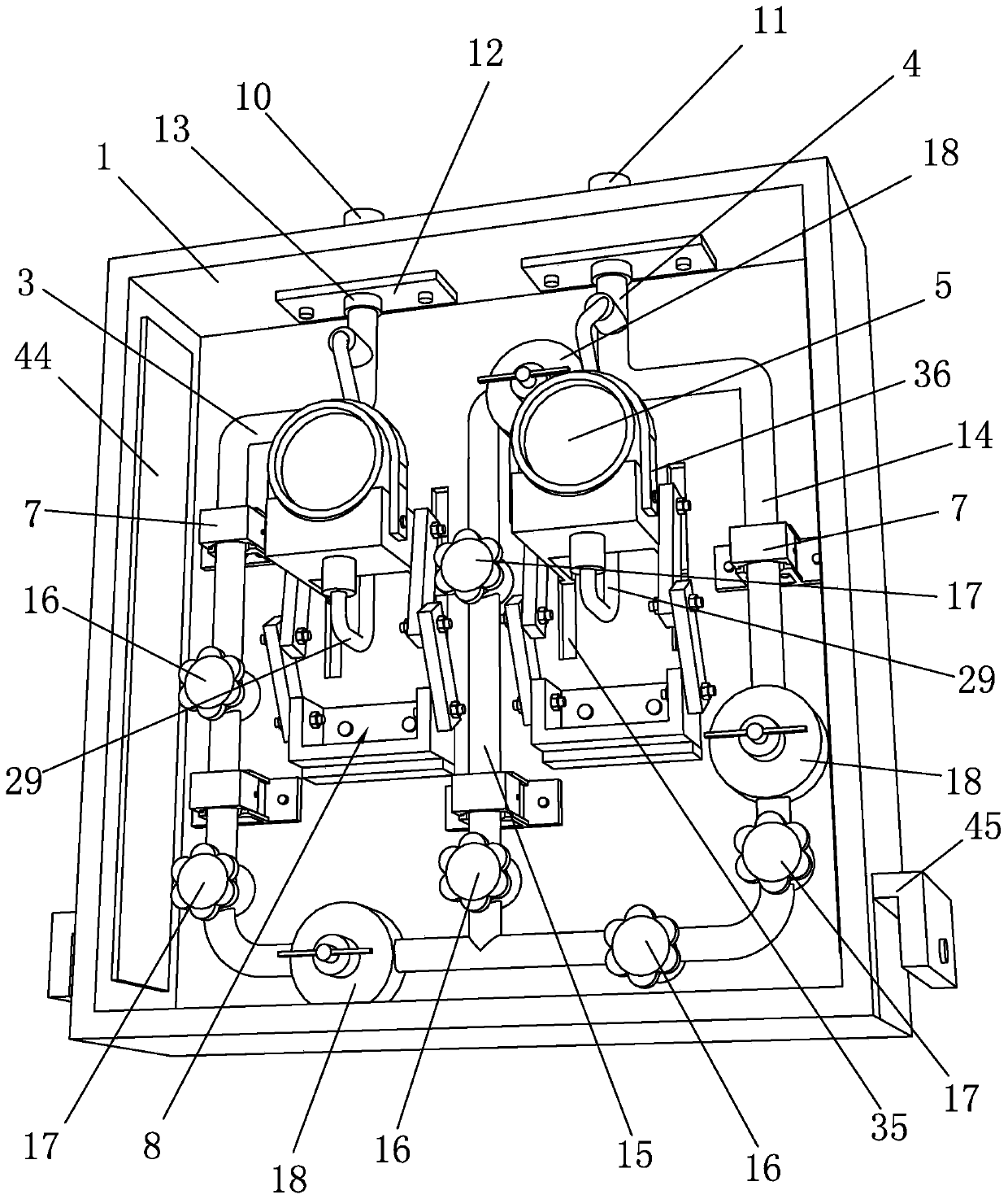
[0029] Such as Figure 1 to Figure 8 As shown, it is a medical gas large-flow decompression device of the present invention, including a decompression box 1 and a box door 2, and the decompression box 1 is provided with an inlet pipe 3 and an outlet pipe 4, and an inlet pipe 3 and an outlet pipe 4 Pressure gauges 5 are arranged on the top, and a suspension frame 6 is also included. The decompression box body 1 is located in the suspension frame 6. The air inlet pipe 3 and the air outlet pipe 4 are all provided with a shock absorber 7. The shock absorber seat 7 is connected with the decompression box body. 1 is fixedly connected to the inner side wall, the pressure gauge 5 is fixedly connected to the inner side wall of the decompression box 1 through the adjustment seat 8, and the box door 2 is provided with an observation window 9; the overall structure of the present invention is reasonable in design and easy to use. The design can facilitate the installation and fixing of th...


PUM


Abstract

The invention discloses a high-flow pressure relief device of medical gas. The high-flow pressure relief device comprises a pressure relief box body, a box door and a suspension bracket, wherein a gasinlet pipe and a gas outlet pipe are arranged in the pressure relief box, pressure gages are respectively arranged on the gas inlet pipe and the gas outlet pipe, the pressure relief box body is located in the suspension bracket, shock absorbing seats are respectively arranged on the gas inlet pipe and the gas outlet pipe, the shock absorbing seats are fixedly connected with the inner side wall ofthe pressure relief box body, and the pressure gages are fixedly connected with the inner side wall of the pressure relief box body by virtue of adjusting seats. According to the high-flow pressure relief device, the suspension bracket is designed, so that the pressure relief box body is conveniently installed and fixed, the stability in placement of the pressure relief box body is guaranteed, and the safety performance is improved; additionally, the shock absorbing seats are designed, so that the pipeline structure in the pressure relief box body is stable, and the pipeline vibrating amplitude caused by gas pulsation during gas conveying is reduced; and the adjusting seats are designed, so that the pressure gages are conveniently installed, the perpendicularity in installation of the pressure gages is guaranteed, the precision of measured values of the pressure gages is increased, and the up-and-down height of the pressure gages can be changed by virtue of the adjusting seats.

Description

technical field [0001] The invention belongs to the technical field of medical gas decompression, and in particular relates to a large-flow medical gas decompression device. Background technique [0002] Medical gas refers to the gas used in medical treatment. Mainly used for treatment, anesthesia, driving medical equipment, medical experiments, culture of bacteria and embryos. Commonly used gases are: oxygen, nitrous oxide, argon, helium, nitrogen, compressed air and mixed gases. Before the medical gas is delivered to the end of use, it needs to be decompressed to decompress the high-pressure gas into the required low-pressure gas. The decompression of medical gases generally uses a special decompression box for decompression treatment. The pressure gauge is an essential part in the decompression box, and the pressure change of the delivered gas can be monitored through the pressure gauge. When the pressure gauge is installed, the verticality of the pressure gauge shoul...

Claims


Application Information

Patent Timeline
Patent Type & Authority Applications(China)
IPC IPC(8): F17D1/04F17D3/01F17D5/00
CPCF17D1/04F17D3/01F17D5/005
Inventor 王盛浪杨益韩沈延辉
Owner ZHEJIANG QIANGSHENG MEDICAL ENG
Learn More