Fence vibration intrusion positioning and mode recognition method based on distributed optical fiber system

A distributed optical fiber, pattern recognition technology, applied in the direction of mechanical vibration actuation of anti-theft alarms, alarms using active vibration detection system, electric alarms, etc., can solve the problem of inability to identify and distinguish shaking, climbing, security systems High false alarm rate, complex and redundant calculation methods, etc., to achieve the effect of less random noise, rich information, and high resolution

Inactive Publication Date: 2019-12-13
广州亓行智能科技有限公司 +1
View PDF8 Cites 19 Cited by
  • Summary
  • Abstract
  • Description
  • Claims
  • Application Information

AI Technical Summary

Problems solved by technology
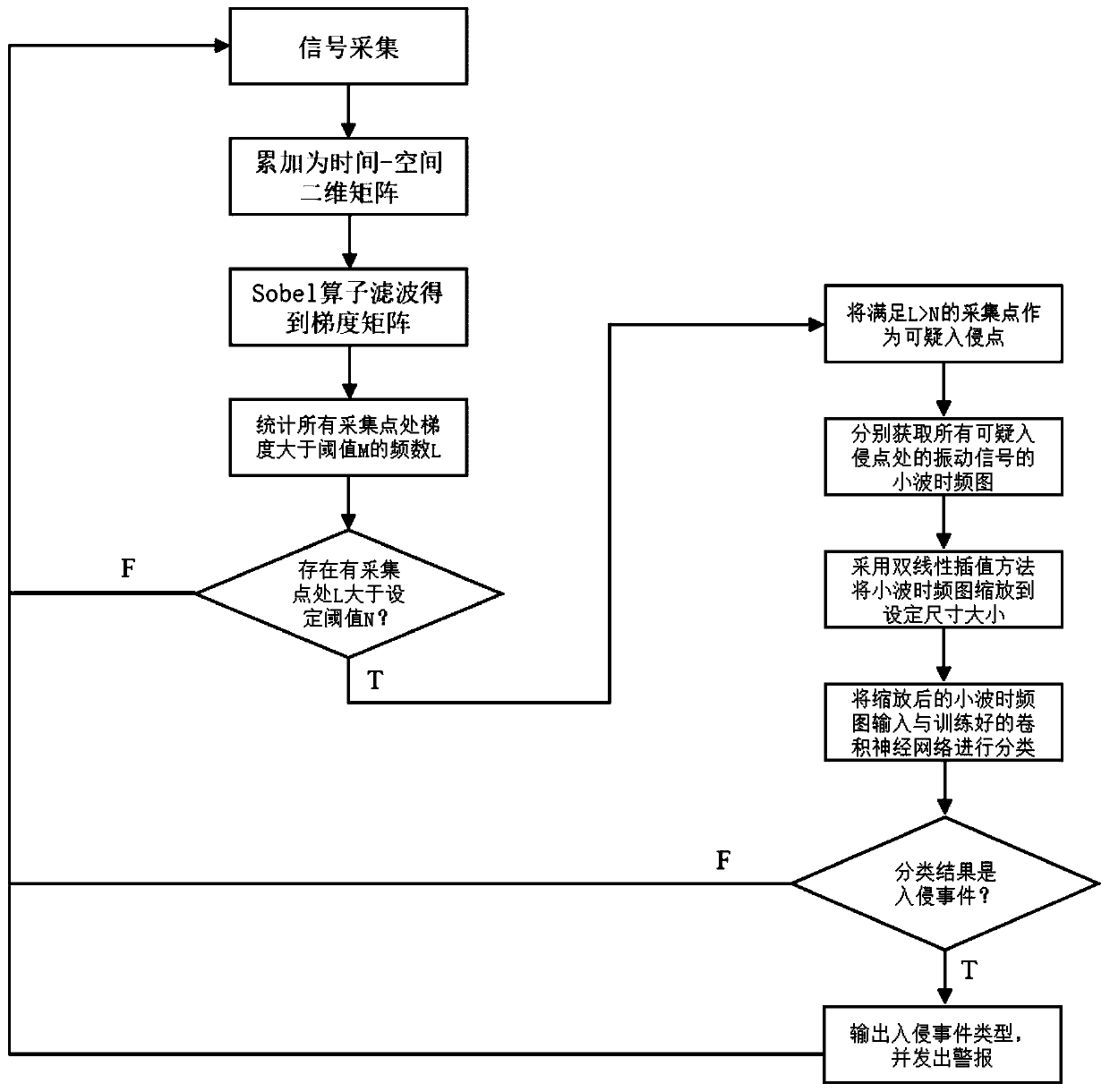
[0003] Most existing fiber optic fence monitoring systems rely on energy thresholds or differential processing methods to identify intrusion behaviors, and can better alarm intrusion behaviors. However, this method cannot identify and distinguish specific behaviors such as shaking and climbing, and Optical fiber vibrations caused by natural environmental factors such as wind and rain are also easily misjudged as intrusion behaviors, resulting in a high false alarm rate of the security system
[0004] In recent years, some fiber optic fence security systems have introduced pattern recognition methods. Although they can classify the specific behaviors of intrusion events, the calculation methods are complicated and redundant, or the need to perform pattern recognition on all fiber optic signals leads to a large amount of data processing. problems, or the method of feature extraction and feature classification in pattern recognition is too computationally intensive, resulting in poor real-time performance of fiber optic fence security system monitoring

Method used


Image

  • Fence vibration intrusion positioning and mode recognition method based on distributed optical fiber system
  • Fence vibration intrusion positioning and mode recognition method based on distributed optical fiber system
  • Fence vibration intrusion positioning and mode recognition method based on distributed optical fiber system

Examples


Embodiment Construction

[0039] The present invention will be described in detail below in conjunction with the accompanying drawings and specific embodiments, and the present invention will be described in detail below in conjunction with the accompanying drawings and specific embodiments. To explain the present invention, but not as a limitation of the present invention.

[0040] It should be noted that the descriptions of “first”, “second” and “third” in the present invention are only for the purpose of description, and should not be understood as indicating or implying their relative importance or implicitly indicating the indicated technology number of features. Thus, features defined as "first", "second", and "third" may explicitly or implicitly include at least one of these features. In addition, the technical solutions of the various embodiments can be combined with each other, but it must be based on the realization of those skilled in the art. When the combination of technical solutions is ...


PUM


Abstract

The invention discloses a fence vibration intrusion positioning and mode recognition method based on a distributed optical fiber system. The method comprises a step of arranging distributed optical fibers on a fence, obtaining a vibration signal of the fence and storing vibration data, a step of accumulating the vibration data of all detection points on the fence into a time-space two-dimensionalmatrix A(x, t), filtering the space-time two-dimensional matrix by utilizing a Sobel operator, counting the times that the position of each detection point is larger than a set threshold value M in atime period after filtering, taking the detection point as a suspicious invasion point if the times that the position of each detection point exceeds the set threshold value M is larger than a set threshold value N and storing original vibration signals of all suspicious invasion points, a step of obtaining wavelet time-frequency graphs of the original vibration signals of all the suspicious invasion points, and a step of inputting the wavelet time-frequency graphs after the suspicious intrusion points are scaled into a convolutional neural network pre-trained by utilizing known event data inadvance. According to the method, the position coordinates and the event type of an intrusion event can be accurately identified, and meanwhile, the requirement of relatively good real-time performance is met.

Description

technical field [0001] The invention relates to the technical field of security systems, in particular to a fence vibration intrusion location and pattern recognition method based on a distributed optical fiber system. Background technique [0002] The security of fences in areas such as highways, warehouses, and prisons is very important. It is of great significance to detect and identify intrusions in time. Among them, it is necessary to accurately locate the location of the intrusion, and it is necessary to filter out wind, rain, and laser source pulses. Interference with factors such as stability, and identify patterns of various intrusion events such as climbing over railings, knocking on railings, and shaking railings. [0003] Most existing fiber optic fence monitoring systems rely on energy thresholds or differential processing methods to identify intrusion behaviors, and can better alarm intrusion behaviors. However, this method cannot identify and distinguish speci...

Claims


Application Information

Patent Timeline
Patent Type & Authority Applications(China)
IPC IPC(8): G08B13/12G08B13/16G08B13/24G08B29/18
CPCG08B13/124G08B13/1609G08B13/2491G08B29/186G08B29/188
Inventor 吕建明刘凯杰唐选文郑志锋
Owner 广州亓行智能科技有限公司
Why Eureka
Try Eureka