
A power generation system and communication device for power generation system

A power generation system and communication device technology, which is applied in the direction of circuit devices, distribution line transmission systems, power line communication applications, etc., can solve the problems of communication interruption, affecting the normal operation of the system, and high cost of communication cables, so as to prevent crosstalk and ensure Effect of subsequent communication speed

Active Publication Date: 2019-12-13
HUAWEI DIGITAL POWER TECH CO LTD
View PDF7 Cites 6 Cited by
  • Summary
  • Abstract
  • Description
  • Claims
  • Application Information

AI Technical Summary

Problems solved by technology

However, DC-side equipment such as power converters are usually far away from the inverter. If RS485 or CAN communication is used at this time, it is necessary to separately excavate a long trench or do overhead treatment during construction. The construction is complicated and the cost of communication cables is high. At the same time, if the communication cable interface is used for a long time, port corrosion and cable damage may occur, which will cause communication quality degradation or communication interruption, affecting the normal operation of the system

Method used


Image

  • A power generation system and communication device for power generation system
  • A power generation system and communication device for power generation system
  • A power generation system and communication device for power generation system

Examples


Embodiment Construction

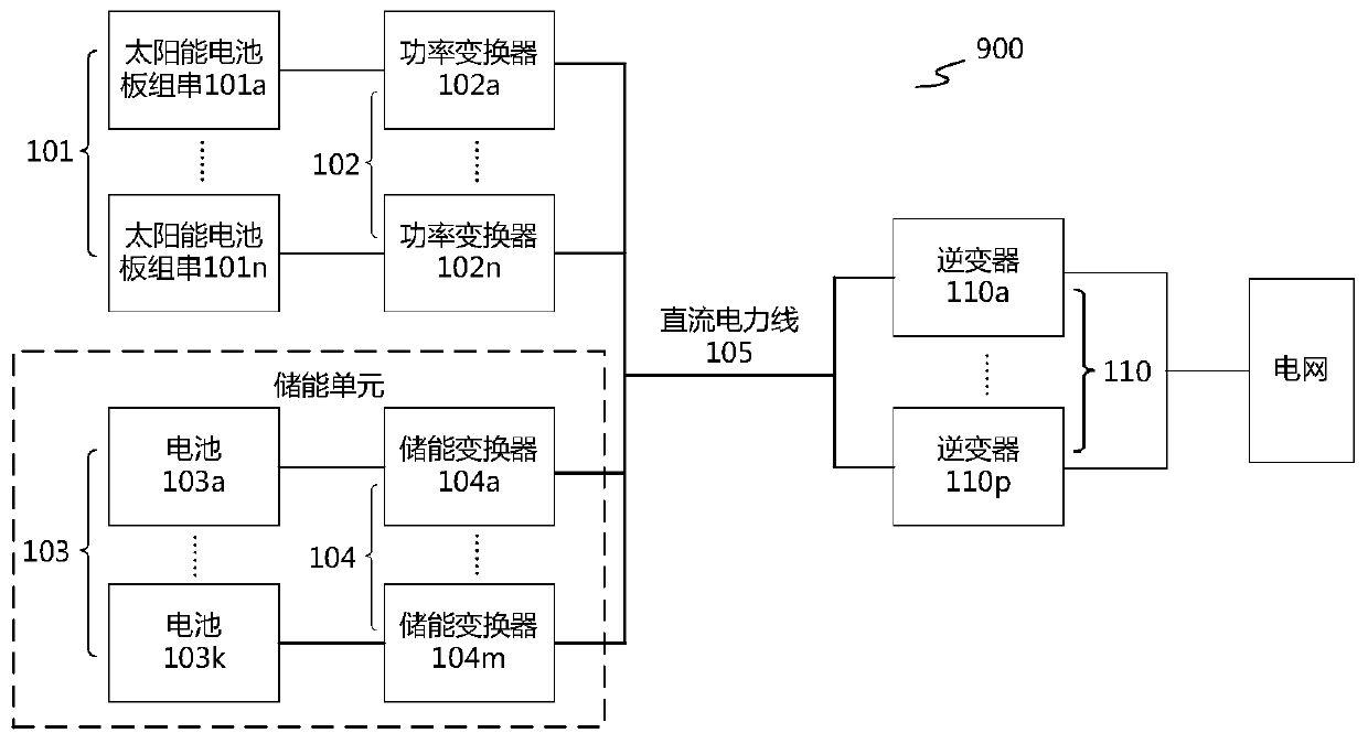
[0058] The application will be further described below in conjunction with specific embodiments and drawings. It can be understood that the specific embodiments described here are only for explaining the application, rather than limiting the application. In addition, for ease of description, the drawings only show a part of the structure or process related to the present application instead of all. It should be noted that in this specification, similar reference numerals and letters indicate similar items in the following drawings. Therefore, once a certain item is defined in one drawing, it does not need to be used in subsequent drawings. For further definition and explanation.

[0059] In the description of this application, it should also be noted that, unless otherwise clearly defined and limited, the terms “set”, “connected”, and “connected” should be understood in a broad sense. For example, they may be fixed connections or alternatively. Detachable connection, or integra...


PUM


Abstract

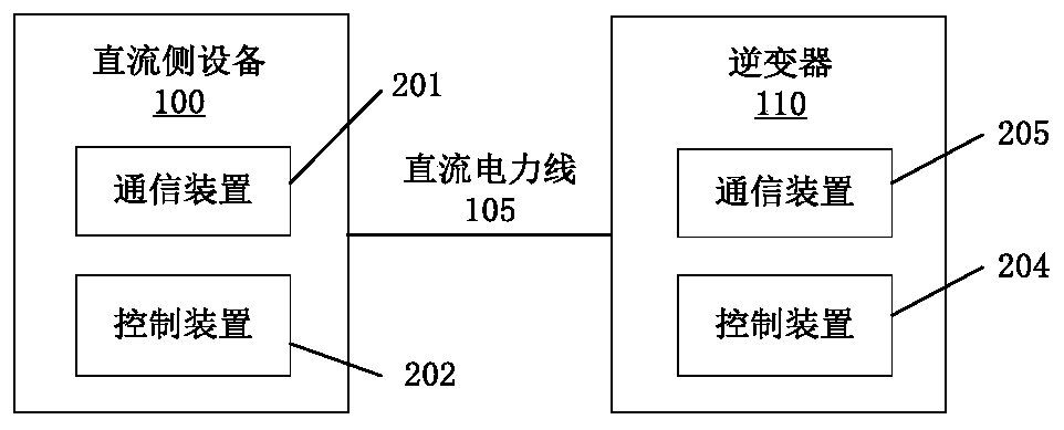
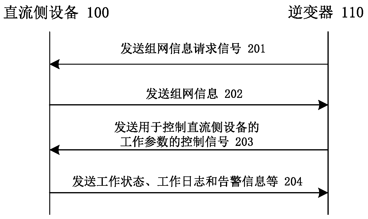
The invention relates to an inverter in a power generation system, which is used for converting direct current input from direct current side equipment into alternating current for supplying power, and comprises a control device and a communication device, the control device is used for controlling the inverter to convert the direct current input from the direct current side equipment into the alternating current for supplying power; the communication device is coupled with the control device and is used for sending a networking information request signal used for requesting networking information to direct current side equipment in the power generation system through a direct current power line; the frequency of the networking information request signal is within a first frequency band, networking information from direct-current side equipment is received, a control signal is sent to the direct-current side equipment, the frequency of the control signal is within a second frequency band, and the control signal is used for controlling working parameters of the direct-current side equipment; wherein the first frequency band is lower than the second frequency band. According to the inverter, crosstalk during networking of the inverter and the direct-current side equipment can be effectively prevented. In addition, the invention also relates to a communication device, DC side equipment and a power generation system.

Description

Technical field [0001] This application relates to a power generation system and a communication device used in the power generation system. Background technique [0002] In the current photovoltaic power generation system, RS485 or Controller Area Network (CAN, Controller Area Network) communication methods are usually adopted between the inverter and the DC side equipment. However, the DC side equipment such as power converters is usually far away from the inverter. At this time, if RS485 or CAN communication is used, a long trench or overhead treatment needs to be separately excavated during construction. The construction is complicated and the communication cable cost At the same time, if the communication cable interface is used for a long time, there may be port corrosion, cable damage, etc., which will cause communication quality degradation or communication interruption, and affect the normal operation of the system. Summary of the invention [0003] The purpose of this a...

Claims


Application Information

Patent Timeline
IPC IPC(8): H04B3/54H04B3/04H02J13/00
CPCH04B3/548H04B3/04H04B2203/5445H04B2203/5458H04B3/32H04B3/06
Inventor 高拥兵张彦忠林天散水伟王晨
Owner HUAWEI DIGITAL POWER TECH CO LTD
Learn More