
Heat conduction device and terminal equipment

A technology of terminal equipment and accommodating tank, which is applied in lighting and heating equipment, structural parts of electrical equipment, decoration through conduction and heat transfer, etc., can solve problems such as excessive temperature rise of mobile phones and affecting heat dissipation

Active Publication Date: 2019-12-13
HUAWEI TECH CO LTD
View PDF5 Cites 3 Cited by
  • Summary
  • Abstract
  • Description
  • Claims
  • Application Information

AI Technical Summary

Problems solved by technology

[0002] As mobile phones become more and more intelligent, their main frequency upgrades will generate more heat. Excessive heat will cause the temperature rise of the mobile phone to be too high, which will affect the heat dissipation.

Method used


Image

  • Heat conduction device and terminal equipment
  • Heat conduction device and terminal equipment
  • Heat conduction device and terminal equipment

Examples


Embodiment Construction

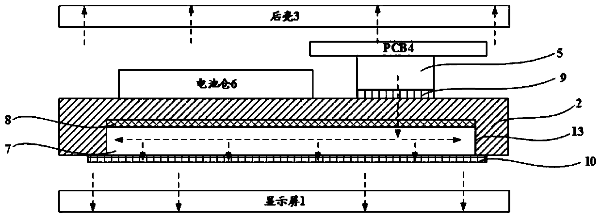
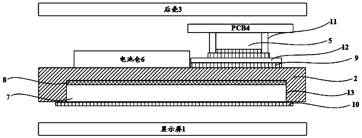
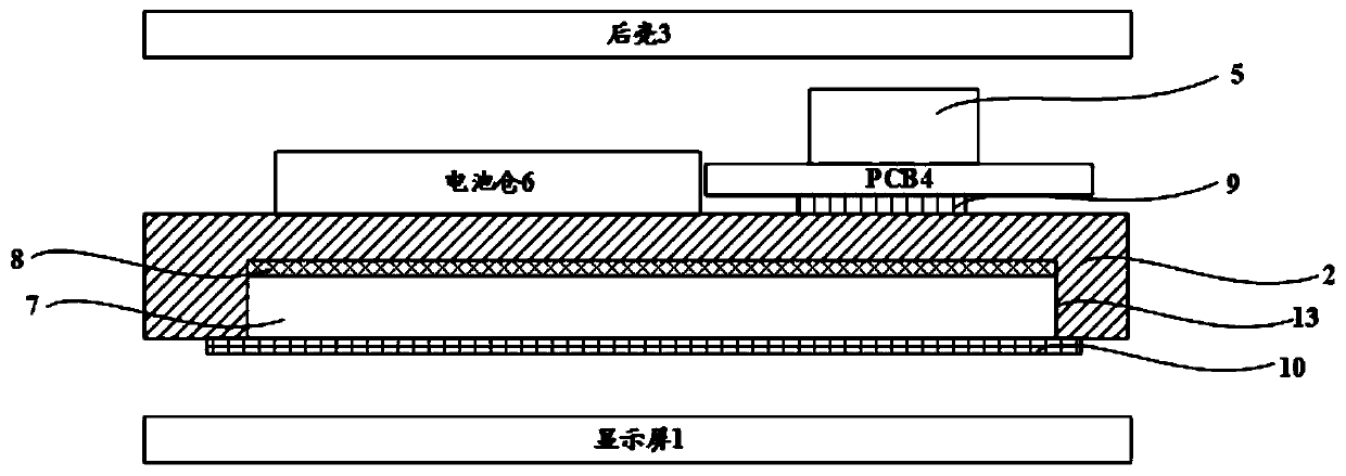
[0062] In order to facilitate the understanding of the heat conduction device provided in the embodiment of the present application, the application scenarios of the heat conduction device provided in the embodiment of the present application will be described first below. The heat conduction device can be installed in terminal devices such as mobile phones, tablet computers, and PDAs , and dissipate the heat generated by heating elements such as chips in the terminal equipment in the terminal equipment. Wherein, the heating element includes but not limited to central processing unit (central processing unit, CPU), artificial intelligence (artificial intelligence, AI) processor, system on chip (system on chip, SoC), power management unit, or other devices that need heat dissipation . The specific arrangement of the heat conduction device in the terminal device will be described in detail below in conjunction with the accompanying drawings, so as to understand the process of th...


PUM

PropertyMeasurementUnit
Thicknessaaaaaaaaaa

Abstract

The invention provides a heat conduction device and terminal equipment, which relate to the field of cooling. The heat conduction device comprises a first cover plate and a second cover plate, whereinthe first cover plate and the second cover plate are connected in a sealed mode; the first cover plate is provided with a plurality of grooves, and a supporting part is formed between every two adjacent grooves; a liquid circulation channel and a gas circulation channel are formed in the groove; the liquid circulation channel is filled with a liquid working medium; the liquid circulation channelis communicated with the gas circulation channel; the liquid working medium is evaporated into gas to enter the gas circulation channel, and the gas is condensed into liquid to enter the liquid circulation channel. When the heat conduction device is applied to the terminal equipment, the first cover plate and a heating element of the terminal equipment can be arranged close to each other, so thatcooling of the heating element is realized through gas-liquid circulation of the liquid working medium in the liquid circulation channel and the gas circulation channel.

Description

technical field [0001] The present application relates to the technical field of heat dissipation equipment, in particular to a heat conduction device and terminal equipment. Background technique [0002] As mobile phones become more and more intelligent, their main frequency upgrades will generate more heat. Excessive heat will cause the temperature rise of the mobile phone to be too high, which will affect the heat dissipation. In order to solve the heat dissipation problem of the mobile phone, a vapor chamber (VC) is usually provided in the mobile phone. [0003] Vapor chamber is a vacuum cavity with fine structure inside and injected with working fluid. At present, the commonly used material is copper, and the working medium is pure water. The working principle of VC includes four steps: conduction, evaporation, convection, and solidification. The heat generated by the heat source enters the plate through heat conduction. , when the steam in the plate diffuses from th...

Claims


Application Information

Patent Timeline
IPC IPC(8): H05K7/20
CPCH05K7/20336H05K7/2039F28D15/0233F28D15/046F28D2021/0029H05K5/0017H05K7/2099
Inventor 孙永富施健杨杰靳林芳孙振
Owner HUAWEI TECH CO LTD
Learn More